


This model combines the screen model and pressure drop correlations of FENSAP with FENSAP-ICE Unsteady for droplets impingement and ice accretion. You should refer to FENSAP - Flow Solution for guidelines on how to set up the screen geometry and input parameters. In the boundary condition menu, select under Icing to activate this model.
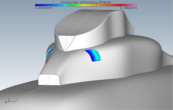
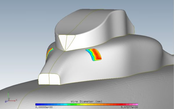
The initial wire diameter grows as the screen collects ice, increasing blockage and pressure and reducing LWC. The screens may be of any orientation and shape. The screen icing model uses the droplet flow direction and the screen surface normal orientation to compute a local collection efficiency at every point on the screen, and determines the ice accretion and wire diameter growth rates. The collection efficiency of the screen and the wire diameter distributions are available in droplet and soln files from DROP3D and FENSAP.
This screen icing model is complemented by introducing an extra term that represents the mass of droplets impinging on the iced screen on the right-hand side of the droplet continuity equation. The term represents the amount of water going through the screen and, therefore, the water collection pattern downstream of the screen. The continuity equation of the droplets can be written in the weak integral form (using integration by part) as:

where  is the Liquid Water Content and
  is the droplets velocity vector. A surface integral, evaluated
only on the screen itself, is added to this governing equation to subtract the water
captured by the screen (a droplet sink):
is the droplets velocity vector. A surface integral, evaluated
only on the screen itself, is added to this governing equation to subtract the water
captured by the screen (a droplet sink):

The constant  indicates the ratio of mass caught by the screen to the total mass
of incoming droplets.
indicates the ratio of mass caught by the screen to the total mass
of incoming droplets.