The run manager provides a graphical interface to configure the specific parameters required to execute a module, such as type of equations to solve, initial and boundary conditions, artificial viscosity and matrix solver settings.
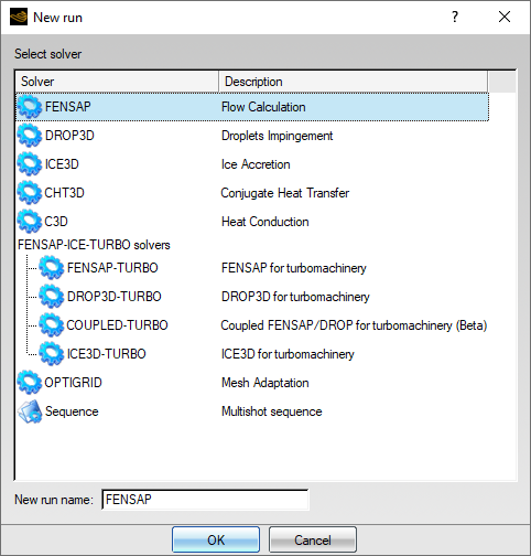
Many separate runs or calculations can be saved within each project. To create a new run, use → or click the new run icon:
A window opens to prompt for the selection of the desired software module. Click the solver name for its selection. The specific name of the calculation should be set in the New run name box, otherwise FENSAP-ICE will select a default, consecutively numbered name. The following figure shows the solver selection interface:
Each run is usually represented by a string of icons that appear to be surrounded by an outline box when the run is selected. The input files, such as the grid and a restart solution (if required), appear at the left of the config icon (blue gear). The output and solution files appear at the right of the config icon. These are usually the current solution file, the heat flux file, the shear stress file, the displaced grid file, the iced geometry tetin file, etc. Their types depend on the solver module.
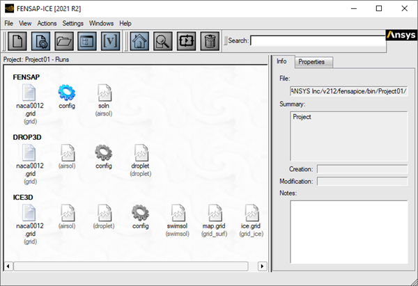
It is possible to create many different runs within the same project, as shown above. The files for each run are saved in a unique directory. To select one run, simply click its name. The selected run is then highlighted.
Note: When more than two runs are displayed, their order can be changed by simply clicking one run and dragging it with the mouse to another location.
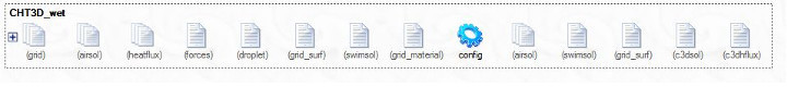
A CHT3D run (Conjugate Heat Transfer) contains a group of modules, each appearing on a separate line. Each line corresponds to either a fluid or a solid domain, with its own config icon. Multiple fluid and solid domains can be assigned in this version. The first line, the lone config icon, represents the CHT3D input parameters that govern the sequence of module execution.
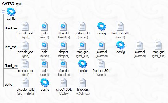
To reduce clutter in the run window, multi-line runs can be folded and unfolded by
clicking the  or
or  button next to the main config icon.
A similar tree structure is used for FENSAP-F/S (aero-elasticity); multishot ice accretion, automatic mesh adaptation cycles with OptiGrid, Sequences, etc.
The list of runs in large projects can be displayed more compactly in hierarchical mode using the View icon:
By clicking this icon, the runs and their corresponding files are listed in a hierarchical view. All input and output files are then shown as subsets of their respective run and project directories. File type, size, creation and modification dates are also displayed.
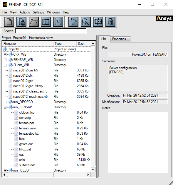
A second click switches the view icon to chronological view. The next click toggles the icon back to the default icon view.
Note: Right-mouse clicking inside any of the runs opens a menu that permits to toggle the view mode.
If the project contains a long list of runs, use the Search box at the top of the FENSAP-ICE window to quickly filter the displayed runs by name.

Table 2.2: Expressions
|
|
|
|
All icons listed to the left of the config icon (blue gear) should be linked to the appropriate files before setting the input parameters.
Note: If a file has already been assigned in another run, for example, a grid to be reused, or a solution file to be used as restart, you can simply drag & drop the icon from that run. A link is then created between these two files and a different icon is used to underline that it is a link to another file:
Tip: To ease data entry, you can also drag & drop the configuration file from one run to another. As a precaution, the input parameters, especially the boundary conditions, should be double-checked before running the new calculation, particularly when the grids are different.
To copy-paste an output file to be used as a restart file in another run:
Select the output file icon of the source run.
Copy (Ctrl+C).
Select the restart file icon of the target run.
Paste (Ctrl+V).
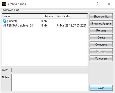
When a calculation is restarted and result files are already present in the run directory, you will be asked to decide if the existing files should be archived for safe-keeping. If selected, the existing files are saved (using the .tar and .zip) in the run directory with a user-defined suffix. Archives are shown in the run with the following icon:

To rename, compress or delete archived solutions, click the archive icon. The existing run can also be replaced with a previously archived one. To perform this operation, click the button.
Some actions can be performed by right-mouse clicking a run. The following menu will appear:
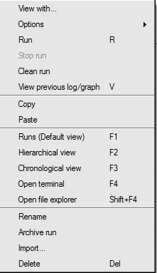
Table 2.3: Menu Options
|
Opens the graphical and input parameter windows. | |
|
Allows restarting the calculation using the current solution file as a restart. | |
|
Opens the graphical window to start the calculation. | |
|
Opens the graphical window and displays the convergence of a previous calculation saved in the run directory. | |
|
Copy the current run or input/output file | |
|
Paste the copied item to its destination. Copy/Paste is equivalent to the drag & drop operation. | |
|
Changes the listing of runs to the default mode. | |
|
Changes the listing of runs to the hierarchical mode. | |
|
Changes the listing of runs to the chronological mode. | |
|
Opens a shell terminal in the selected directory. The terminal properties can be customized in Settings → Preferences → Applications → TERMINAL. | |
|
Allows changing the name of the run directory. | |
|
Allows archiving a previous run. This is helpful if you want to rerun one calculation and keep track of all previous calculations saved in the same directory. | |
|
Imports a run directory (grid file, input parameters, solutions). | |
|
Removes the run directory from your account. |
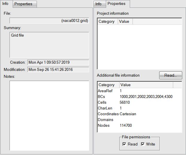
The right side of the Project Manager window provides some extra information on these subjects:
When selecting a file, the menu indicates file location, summary, creation and modification dates.
When selecting a grid or solution file, the menu (Read option) lists some of the important variables in these files (for example, number of nodes, elements, etc.).
The file permission can be changed with . Comments can be added in the Notes field.