


No specific boundary conditions are required for ICE3D, except for sink boundaries. Exits will automatically apply a flow-through condition where the water is free to leave the domain and ice displacement can take place if there is any icing on the corresponding exit nodes.
Although ICE3D can automatically remove the water film in regions where water pooling may occur, such as trailing edges, wing tips, etc., in some cases it may be necessary to specify a sink boundary condition manually.
To remove water locally, a sink can be associated to multiple wall boundary conditions (See FENSAP-ICE File Formats). The sink is applied to all faces of that particular boundary.
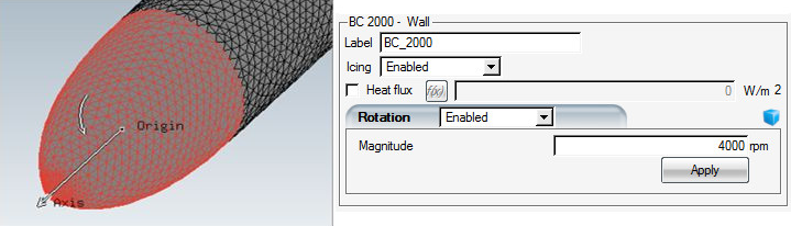
To account for rotation on rotating surfaces of revolution, such as propeller
spinners and engine center cones, a rotation boundary condition can be enabled on
wall families. To use this boundary condition, choose
in the Rotation section of the selected wall family. Enter a
magnitude for the rotation rate and click apply. The axis of rotation is detected
automatically and displayed in the 3D viewer panel. The direction of rotation
follows the right-hand rule convention. To reverse the direction of rotation, simply
add a minus (-) sign in front of the rotational velocity
magnitude and click Apply.
Note: The flow solution for the spinner should also contain the surface rotation effects, using the same rate and direction of rotation. If the ICE3D setup is done using the drag & drop functionality from FENSAP and DROP3D configurations, the rotation settings in the FENSAP run will automatically be carried over. If a different flow solver is used, then the correct values for the rotation rate and direction should be imposed manually to match the flow solution.
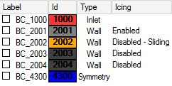
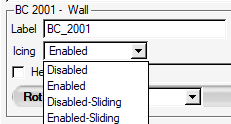
This option allows the additional characterization of walls on which ice accretion has been disabled as sliding boundaries. Sliding boundaries are useful when ice accretion on one surface completely dominates over the neighboring surfaces (the sliding boundaries). The resulting uneven ALE mesh displacement could deform the grid to such an extent that elements become degenerate, making it impossible to obtain a usable 3D displaced grid during multishot ice accretion (See Generate a 3D Displaced Grid).
Important: This option should be used only after careful examination of the surface collection efficiency, to estimate whether displacement would lead to a degenerate grid, or if problems with grid displacement have been encountered.
To use this option, click a wall boundary in the list of boundary surfaces and select the or option in the Icing drop-down menu. ALE will then ensure that the grid nodes laying on this wall will slide on their original surface rather than grow outward, preventing the grid from becoming degenerate. The option will continue to solve the mass and energy equations of ice, but will not displace the wall if it ever accretes some ice. Instead, these walls are used to slide the ice that accretes on adjacent walls.
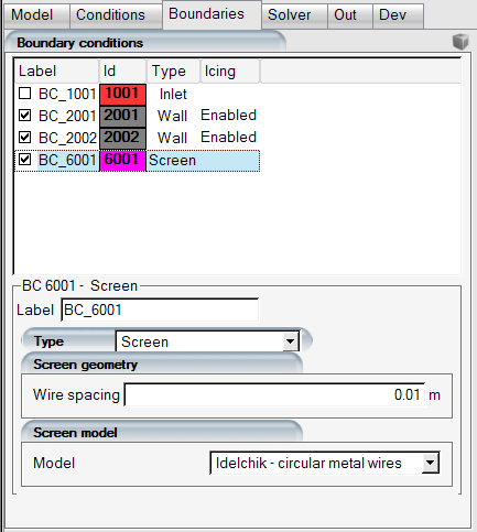
FENSAP-ICE has the capability to model wire-mesh screens and their effect on the airflow and droplet fields. As droplets impinge on the screen, ice accretion takes place increasing the blockage and momentum losses. To simulate this effect, set the Type of the 6000 boundary condition family to . Screen boundary conditions should have a non-zero wire spacing defined so that porosity can be calculated. This spacing and the screen model should match the values set in the FENSAP and DROP3D steps to ensure consistent results. Configuring ICE3D using drag-and-drop from a DROP3D configuration will cause ICE3D to automatically inherit the type and spacing for the screen boundaries.
The screen icing model assumes that all droplets hitting the wire mesh of the screen freeze on contact (rime ice), and progressively increase the blockage of the passages. The screen may be subject to spatially variable rates of ice accretion, depending on local flow and droplet conditions. The wire diameter field is calculated before the wall icing calculations take place and is saved within the roughness.dat file with the timebc variable code 60. To visualize this, the original grid and the roughness.dat file can be loaded within Viewmerical in TIMEBC mode.
In multishot simulations, FENSAP reads the roughness.dat file to take the new roughness and/or screen wire diameter output by ICE3D. FENSAP and DROP3D take into account the new wire diameter when calculating total pressure and LWC drop across the screen for the subsequent shots. Wire diameter is then saved in the FENSAP soln file, which ICE3D uses as source data for the next shot.
Screen icing can also be enabled in unsteady icing when running in Combo mode, where, for each physical air flow time step, ICE3D calculates the increase in wire diameter and provides it to FENSAP and DROP3D for the next time step.
The effect of iced screens will only be apparent if a new airflow solution is computed with the modified screen wire diameter distribution.
Tip: The effect of screen icing on air and droplet flows are only visible in unsteady or multi-shot icing simulations. The blockage increases and LWC reduction are compounding effects that are more accurately captured with short multi-shot durations. If only interested in the pressure and LWC loss history and not the ice shapes, you can skip the ice shape displacement and remeshing steps by de-activating under Out → Advanced, as well as setting the Grid displacement mode to .
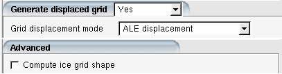
Doing so will run all the shots on the same initial mesh, reducing the number of iterations required to converge each shot since the mesh topology remains constant, while updating screen wire diameter distribution, blockage effects, and continuing to accumulate surface ice growth without displacing the mesh.