


The solution files of ICE3D can be saved in FENSAP format (See FENSAP-ICE File Formats). The following files are created:
Table 6.1: ICE3D Solution Files
| iceconv.dat | Surface temperature/film height convergence information |
| map.grid | 3D surface grid before ice accretion |
| ice.grid | 3D surface grid after ice accretion |
| ice.tin | CAD of the iced surface in ICEM CFD TETIN format |
| swim.log | Reference/initial conditions and convergence messages |
| swimsol | ICE3D solution at each grid point on the wall surfaces |
| timebc.dat | Ice displacement information |
| roughness.dat | Surface sand-grain roughness distribution |
| swim.log | Reference/initial conditions and convergence messages |
| ice.stl | CAD of the iced surface in SLD format |
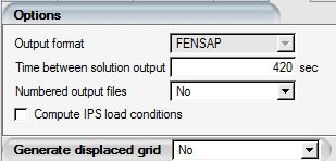
The solution files can be saved at intermediate time levels by setting the Time between solution outputs. If the Numbered output files option is activated, the file numbering will follow the solution output instances.
ICE3D can output a 3D grid displaced by the accumulated ice on the solid boundaries. This grid can then be used directly by the flow solver to compute performance degradation or to perform multishot ice accretion without manual remeshing.
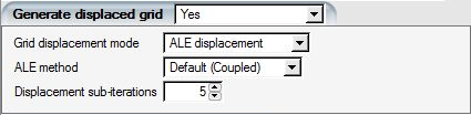
To output the displaced grid file, saved in FENSAP format, select Yes in the Generate displaced grid box. The displaced grid will appear inside the run folder, with the same name as the original 3D grid and a .disp suffix appended to it, for example grid.disp.
Note: For the volume grid displacement, ICE3D invokes FENSAP and its ALE (Arbitrary Lagrangian-Eulerian) approach. The Default (Coupled) ALE solver mode yields a better quality mesh near the surface compared to the Uncoupled solver mode. This is therefore the recommended grid displacement method.
If FENSAP cannot generate a displaced grid ( for example the displacement is too large or the resulting grid has degenerate elements), load the ice.tin file into ICEM CFD and generate a new grid with the iced surface.
Tip: For large or complex ice accumulation, the displaced grid may not be of good CFD quality. To improve its quality, you are invited to use OptiGrid in mesh smoothing mode instead of manual remeshing, in order to save time.
ICE3D can also be used to compute the required heat flux distribution that prevents ice formation on the walls of a geometrical model. When used in this mode, ICE3D conducts a mass and thermal balance for two scenarios: a running wet scenario and a fully evaporative scenario. In the running wet scenario, the required heat flux represents the minimum amount of heat flux required to maintain a film of water at zero degrees Celsius (no ice) at each cell/element of the surface. In the fully evaporative scenario, the required heat flux represents the minimum amount of heat flux required to evaporate all water droplets that impact each cell/element of the geometrical model.
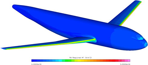
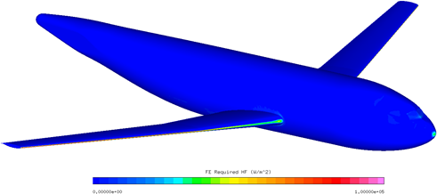
The required heat flux distribution provides an insight on the amount of heat/energy that an IPS (Ice Protection System) should deliver in order to prevent ice formation over a geometrical model at a specific in-flight icing condition.
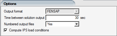
To activate this special mode, select Compute IPS load conditions in the Options menu of the Out panel and then press on Run to execute this simulation.
Note: Currently, this feature only supports Appendix C type droplets. SLD or crystals are not yet supported.
Both running wet and fully evaporative results are stored inside a single swimsol file. Therefore, they can be viewed with Viewmerical.
Thirteen fields are present in the swimsol file.
Mass Caught (kg/s/m2): Mass flux of water droplets that impact on the surface of the model.
RW Film Height (microns): Continuous water film height that satisfies running wet conditions.
RW Evaporation MF (kg/s/m2): Mass flux of evaporation that satisfies running wet conditions.
RW Required HF (W/m2): Required heat flux that satisfies running wet conditions
RW Water Droplet HF (W/m2): Energy flux due to water droplets that satisfies running wet conditions. This heat flux accounts for water droplet enthalpy and kinetic energy.
RW Evaporation HF (W/m2): Heat flux of evaporation that satisfies running wet conditions.
RW Radiation HF (W/m2): Radiation heat flux that satisfies running wet conditions
RW Convection HF (W/m2): Convective heat flux that satisfies running wet conditions.
FE Required HF (W/m2): Required heat flux that satisfies fully evaporative conditions.
FE Water Droplet HF (W/m2): Energy flux due to water droplets that satisfies fully evaporative conditions. This heat flux accounts for water droplet enthalpy and kinetic energy.
FE Evaporation HF (W/m2): Heat flux of evaporation that satisfies fully evaporative conditions.
FE Radiation HF (W/m2): Radiation heat flux that satisfies fully evaporative conditions.
FE Convection HF (W/m2): Convective heat flux that satisfies fully evaporative conditions.
In addition, two heat/energy tables are printed inside the log file, swim.log. Each table reports the thermal balance per wall family for fully evaporative and running wet conditions. Each heat/energy source and sink satisfy the following equation.

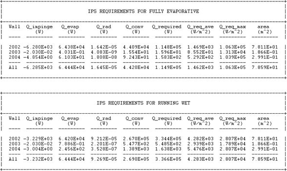
In these tables, the first column coincides with the wall family number of the external grid. The other columns correspond to heat/energy sources or sinks.
Q_impinge: Energy due to water droplets enthalpy and kinetic energy change.
Q_evap: Heat due to evaporation.
Q_rad: Heat due to radiation.
Q_conv: Heat due to convection.
Q_required: Required heat to prevent ice formation.
Q_req_ave: Average heat flux to prevent ice formation.
Q_req_max: Maximum required heat flux to prevent ice formation.
Area: Area of the wall family.