


FENSAP-ICE solves steady-state airflow, water droplet/ice crystal impingement and the corresponding ice accretion on multiple stationary and rotating components.
Each component in a single simulation is solved independently and linked to adjacent components through interfaces. The mixing-plane algorithm is used to transfer boundary conditions between interfaces. Since all grids are separate, non-matching grids and blade rows with unequal pitch are supported. Usually the grids used in turbo simulations are rotationally periodic, however it is possible for a periodic grid to interface with a non-periodic grid as long as the interface on the non-periodic side is axisymmetric. The non-periodic grid orientation does not need to align with the periodic components, as the mixing plane boundary condition transfer is designed to work with local cylindrical coordinates at each interface. This allows an aircraft with nacelle that is not exactly aligned with any of the Cartesian axes to be connected to an engine aligned in any direction.
This section describes the general features in FENSAP-ICE required to set up an airflow, droplet/ice crystal impingement or ice accretion in a turbomachine.
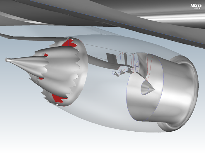
Figure 9.1: Turbo Simulation Setup Featuring Rotationally Periodic Internal Components with a Full 3D External Grid That Contains a Wing-Body-Nacelle-Pylon Configuration
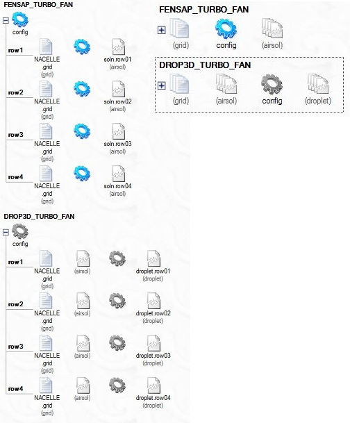
A series of individual components (rows) is required to set up a multi-row simulation. A new run is created either through the → menu or by clicking the new run icon in an existing project window:
Three simulation types are available to you:
FENSAP-TURBO - airflow simulations
DROP3D-TURBO - droplet and ice crystal impingement
ICE3D-TURBO - ice accretion simulations
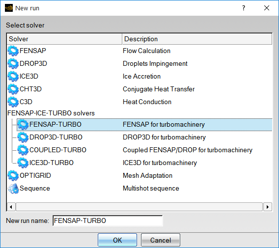
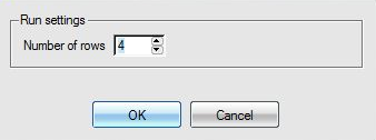
Once a simulation type and suitable run name are chosen, a window will appear to identify the number of components:
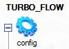
A global config icon, identified by a blue gear, contains the configuration settings for this run:
When several runs appear in the project, the readability of the project window can be improved by clicking the or buttons on the left of each individual run to collapse or expand each run:
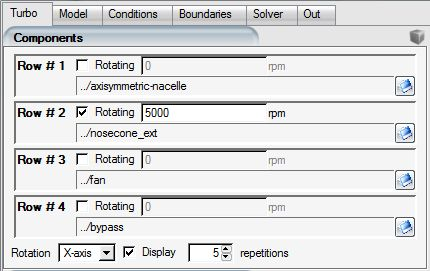
The Turbo panel is available in every FENSAP-ICE-TURBO run window, and can be accessed by double-clicking the config icon. The Turbo panel allows you to configure grids and their interfaces and set up rotation speeds for each component.
The Advanced section allows you to define interface algorithms and the frequency of transfer between boundaries.
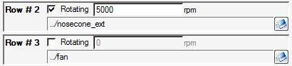
The grid file is assigned in the Components section of the Turbo panel using the Browse buttons (blue folder icons) on the right side of each Row.
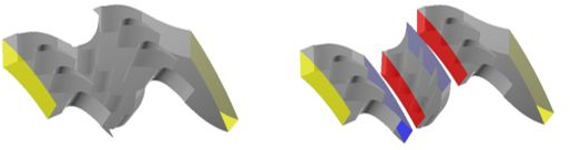
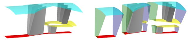
The grids do not necessarily have to be arranged sequentially; staggered arrangements are also supported. The following figures show examples of supported configurations.
To assign the grid directly in the project window, right-click the grid icon and select the appropriate grid file with the option from the pull-down menu.
Important: If the assigned grid is replaced by a different one, it is imperative to review the Boundaries panel to ensure that the boundary values are still valid.
A rotational speed for any component is defined by adding a check mark next to the Rotating check box at the right of the row number and imposing the appropriate rotation speed, in revolutions per minute (rpm).
A negative or positive sign in the rotation speed indicates the direction of rotation relative to the axis of rotation.
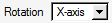
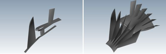
To verify the periodicity of components and display periodic repetitions of the grid, specify the Rotation axis, either X, Y, or Z, using the drop-down menu located at the bottom of the Components panel.
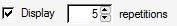
Click the Display check box and define the number of repetitions. Multiple instances of the periodic components will be displayed.
An interface is created by pairing the adjoining boundaries in neighboring rows.
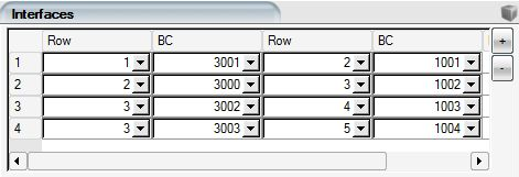
Interfaces are automatically generated the first time the configuration panel is opened under the assumption that the rows are all arranged in sequential order (purely axial geometry). The automatic assignment should be reviewed and edited, if necessary, before proceeding to the input parameters.
To add or remove an interface, use the or buttons. Each component is identified by its row number. Typically, the exit of one component should be coupled with the inlet of its downstream component. As soon as surfaces from neighboring components are coupled to form an interface, they are marked as disabled in the Boundaries panel, since no user-defined boundary condition can be applied on these surfaces.
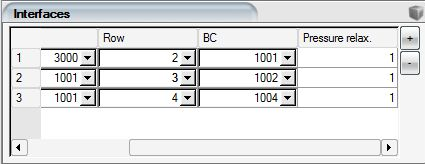
The interface Pressure relax. is used when pressure boundary conditions are updated at an exit. The relaxation factor is set to a default value of unity but could be reduced should convergence instabilities arise.
The settings indicated in this section apply to airflow simulations in a FENSAP-TURBO run.
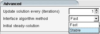
The Update solution every (iterations) parameter defines the frequency with which the interfaces boundary conditions are updated. This parameter is set to a default value of unity but can be increased if the convergence of the system is slow.
Two Interface algorithm methods are available for the application of boundary conditions at the interfaces:
Table 9.1: Interface Algorithm Methods
| Fast | It is the simplest and quickest method but may be unstable when the mesh is very fine at the interface. |
| Stable | Provides a smooth variation of the interface conditions at each update. It is more robust but may reduce the convergence rate compared to the Fast option. This is the default setting. |
The Initial steady-solution sets the number of iterations to be completed in each component before the first update of the interfaces is allowed.
In order to properly post-process turbo (airflow, particle and ice) solutions inside CFD-Post Turbo, it is recommended to assign a Turbo part (Hub, Shroud, Blade, Inlet, Outlet, Periodic1, Periodic2, Other) at each boundary surface of the computational domain.
and turbo parts are automatically detected by the graphical user interface of FENSAP-ICE at execution time.
, , , , and must be manually selected.
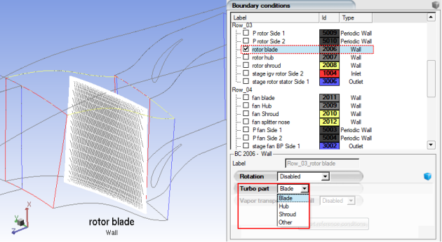
Other is used to define boundary surfaces that cannot be represented by another Turbo part. In this manner, Other surfaces are ignored by CFD-Post Turbo and should be manually selected in the graphical user interface of FENSAP-ICE.
For more details regarding post-processing of (airflow or particle) solutions using CFD-Post Turbo, consult FENSAP-ICE Turbo.