


All the parameters that control the execution of the droplet module are set to default values. You may change some of these parameters once you have gained a sufficient confidence level.
To improve the performance of the iterative matrix solver, the terms associated with the temporal operator of the droplets equations can be added to the Jacobian matrix (note that these terms do not affect the residuals). The addition of these terms, proportional to 1/Δt, increases the diagonal dominance of the Jacobian matrix and therefore improves the convergence of the iterative matrix solver. The solution is then advanced in time until the time derivative terms become zero, or the flow field reaches steady-state.
The choice of the local time step, for an element, is based on a stability
analysis of the explicit-Euler centered finite difference scheme, which provides a
maximum theoretical  . In DROP3D, the time step is then selected as:

The droplets solution is advanced in time, with a  that varies from one cell to another, until steady-state is
reached. At each time step, only one Newton iteration is performed to linearize the
system. The linear matrix system is solved using a GMRES approach.
that varies from one cell to another, until steady-state is
reached. At each time step, only one Newton iteration is performed to linearize the
system. The linear matrix system is solved using a GMRES approach.
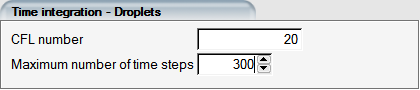
Tip: Recommended values for the CFL number range between 10 and 20. If convergence problems are encountered, lower the CFL number.
Smaller droplets are affected by the airflow more than the larger ones and generally take more iterations to converge. If the quality of the grid is good and the run is stable, the CFL number can be increased to 100 or more to achieve convergence in a reasonable number of iterations.
Maximum number of time steps is the maximum number of iterations of DROP3D. If the solution has not converged sufficiently at the end of the iteration process, restart the droplets calculation from the previous solution (See Restarting DROP3D) and perform additional iterations.
The Streamline upwind (SU) technique adds artificial viscosity exclusively in the direction of the droplet velocity as an anisotropic artificial diffusivity. In tensor form the artificial viscosity coefficient can be written as:

where

This coefficient is automatically computed by DROP3D and cannot be modified.
To address spurious oscillations that can occur in the cross-flow direction, the SU scheme is complemented with a user-set crosswind diffusion amount, which acts exclusively in the cross-flow direction. The default baseline magnitude is 10-5 and it scales with element size, where its power reduces as elements get finer.
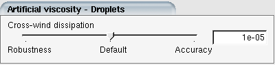
In the case of structured grids, the LWC discontinuity present in the shadow zone can result in node-to-node oscillations in the cross-flow direction for certain droplet sizes. These can be suppressed by dragging the cross-wind dissipation slider to Robustness,10-4. In general, the effect on the collection efficiency will be negligible, however, case specific experimentation is recommended before adopting a higher value.
Convergence Criteria
Two parameters control the DROP3D convergence stopping criteria: the overall residual of the governing equations and the change in total beta (cumulative water catch) on all the wall surfaces. Total beta is a derived quantity and therefore may require more iterations to fully converge. Change in total beta usually does not exhibit a monotonous behavior, therefore the activation of this stopping criterion is delayed until the average residual of the last 20 iterations is below the specified criterion.
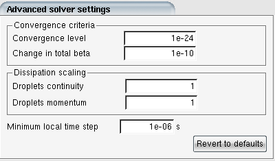
Dissipation Scaling
The amount of streamline artificial dissipation can be increased or decreased by further adjusting the scaling parameters. These are only available if is checked in → → tab. It is strongly recommended that these values are kept as 1 for accurate particle impingement solutions. If the computations have difficulty converging, the remedy should be looked elsewhere. It could be that the boundary conditions are not set properly, the airflow has not fully converged, or the grid quality is inadequate overall or in certain parts of the domain. Increasing cross-wind dissipation should be tried before resorting to increasing overall dissipation scaling.
The maximum value for the dissipation scaling is limited to 2. Entering higher values will result in a warning message logged in DROP3D.
Minimum local time step
This option is useful when DROP3D solution appears to converge very slowly near the walls, especially when very high aspect ratio structured grids are used. DROP3D uses a CFL-based local time stepping approach for steady-state integration of it’s PDEs. The local time step is based on cell size and droplet speed. In some cases where the cell aspect ratios are very high, the local time step may reduce to extremely small values, delaying convergence. This behavior is usually observed with structured turbo-machinery grids where the grid cells near the blade/hub intersections are quite stretched. Unphysical transients may take many iterations to wash-out in such areas when this is the case. Minimum local time step option helps alleviate this issue. The default value is set to 1 micro second (1e-6s). Increasing this value may further accelerate convergence but should be done with care.