


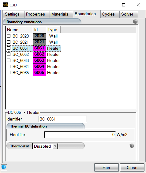
All boundary surfaces present in the grid file are listed in the Boundary conditions panel. The boundary conditions define the default state of walls or heaters. The heating elements should be set to zero heat flux in this panel, indicating that they are inactive at all times, unless otherwise specified in the Cycles panel.
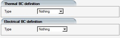
Two types of boundary definitions are available for wall boundaries, according to the type of problem being solved: Thermal BC Definition and Electrical BC Definition.
Several types of conditions can be applied on the wall boundaries of the solid:
Table 7.2: Thermal Boundary Conditions
| No specific boundary conditions are applied to this boundary by C3D, but will be applied automatically by other codes, such as CHT3D. In standalone C3D operation, these boundaries will receive an adiabatic boundary condition (q = 0) instead. | |
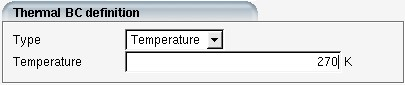
| A prescribed temperature is imposed on all nodes of this boundary. | |
| A constant, prescribed heat flux is imposed. A zero heat flux can be used for an adiabatic boundary condition or a symmetry condition. | |
| Indicates that a heat transfer coefficient h is imposed on all surfaces of this boundary condition family. The reference temperature must also be specified in the Temperature box. |
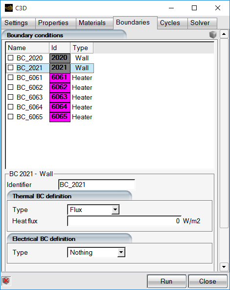
Boundary conditions for all surfaces other than heating pads must be assigned. When a wall surface is selected, the BC definition box will appear.
These boundary conditions can be set to:
: No specific boundary conditions are applied to this boundary condition index by C3D, but will be applied automatically by other codes, such as CHT3D.
: The prescribed temperature
 is imposed at all nodes of this boundary.
: The prescribed heat flux will be imposed on all surfaces of this boundary.
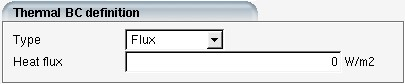
The heat flux is defined as:

where  is the heat conduction coefficient and
  is the surface normal.
Mixed: The heat transfer coefficient (h) and the reference temperature will be imposed on all surfaces of this boundary. In the case of a moving fluid, this heat transfer coefficient is the convective heat transfer coefficient and the reference temperature is the recovery temperature.
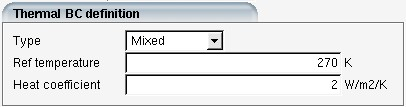
This coefficient is defined as:

where  is the reference temperature.
Several types of conditions can be applied on the wall boundaries of the conducting solid:
Table 7.3: Electrical Boundary Conditions
| No specific boundary conditions are applied to this boundary C3D. | |
| Used to impose a prescribed voltage on all nodes of this boundary. | |
| A constant, prescribed current is imposed. On the external surface of a conductor, this should be set to zero. | |
| Indicates a boundary that is embedded in the mesh. It can be the interface of two different materials, or internal to a material. In general these do not impose a boundary condition but are used to visualize and post-process the solution at this location. |
One thermostat can be assigned to each heating pad. Select to view more options.
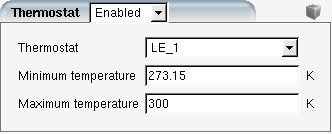
The Thermostat can be selected from the list defined in Electrothermal Model. The thermostat will maintain the temperature at
its location between the specified Minimum temperature and
Maximum temperature. To verify the location of the
thermostat, click the on the ![]() icon to display its position in the graphical window.
icon to display its position in the graphical window.
C3D supports two heater pads models.
A heat flux applied on a boundary surface. The surface must be identified by a boundary index ranging from 6,000 to 6,999 (See FENSAP-ICE File Formats).
The heating pad can either be embedded inside the solid (internal surface) or located on the outer surface. In the Boundary conditions panel the heating pad should initially be set to zero Heat flux, indicating that is inactive by default. Its activation must be specified in the Cycle panel box.
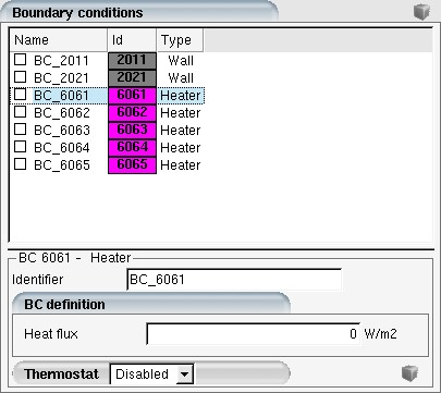
In the Boundary conditions panel the heating pad should initially be set to zero heat flux, indicating that is inactive by default. Its activation must be specified in the Cycle panel box. The value specified for Heat flux in the Boundary conditions panel is a global value which will be applied as baseline value for this heater pad, throughout the entire length of the simulation. If the heater pad flux value is changed in the in the Cycles panel, the heater pad will use that new value for the length of the state block.
Note: Prior to R18.0, the heater pad values could have a single value, which was set-up in the Boundary conditions panel. It is now suggested to set-up the heater pad in the Cycles panel, and keep the global value to 0.
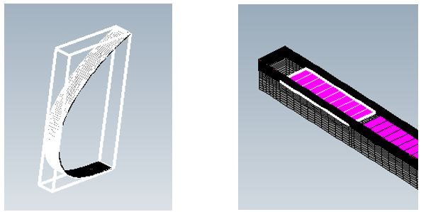
Power density applies to a material acting as a volume heat source, as shown in white in the figure below.
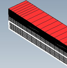
This option requires the definition of the material properties for the heater pad (See Properties), the identification of the material as a Volume heat source (Materials), followed by its Power density value. (See Boundary Conditions Cycles).
In this case heat conduction through the heating pad material can be simulated even when the volume heating source is turned off.