VMFL021
VMFL021
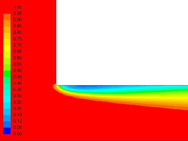
Cavitation
Over a Sharp-Edged Orifice Case A: High Inlet Pressure
Overview
| Reference | W.H. Nurick, “Orifice Cavitation and Its Effects on Spray Mixing”. Journal of Fluids Engineering, Vol.98, pp. 681-687, 1976 | ||
| Solver | Ansys Fluent, Ansys CFX | ||
| Physics/Models | Turbulent multiphase flow with cavitation and phase change | ||
| Input File |
| ||
| Project Files | Link to Project Files Download Page |
Test Case
A steady, axisymmetric, multiphase (water/steam) flow, with phase change taking place. Due to sudden contraction a low pressure region occurs near the sharp edge which results in cavitation. Figure 57: Flow Domain depicts the orifice geometry. Flow direction is from left to right.

| Material Properties | Geometry | Boundary Conditions |
|---|---|---|
|
Liquid: Water Density : 1000 kg/m3 Viscosity: 0.001 kg/m-s Gas: Water-Vapor Density: 0.02558 kg/m3 Viscosity: 1.26x10⁻⁶ kg/m-s |
L1 = 1.60 cm L2 = 3.20 cm r1 = 1.15 cm r2 = 0.40 cm |
P1 = 250,000,000 Pa P2 = 95,000 Pa T = 300 K Pvapor = 3,540 Pa |
Analysis Assumptions and Modeling Notes
The flow is steady and incompressible. Pressure based solver is used. Fluent uses standard k-ε model with standard wall functions for the turbulence model while CFX uses SST. The Zwart-Gerber-Belamri cavitation model is applied together with mixture multiphase model.
For analysis of results, we calculate and compare the discharge coefficient with the experimental data.
The coefficient of discharge,  ,
is the ratio of the mass flow rate through the nozzle to the theoretical
maximum mass flow rate:
,
is the ratio of the mass flow rate through the nozzle to the theoretical
maximum mass flow rate:

In the above equation,  is the mass flow rate as calculated
by the CFD solver.
is the mass flow rate as calculated
by the CFD solver.