VMFL020
VMFL020
Adiabatic
Compression of Air in Cylinder by a Reciprocating Piston
Overview
| Reference | L.D. Russell, G.A. Adebiyi, Classical Thermodynamics, Saunders College Publishing, Philadelphia, PA, 1993 | ||
| Solver | Ansys Fluent, Ansys CFX | ||
| Physics/Models | Dynamic Mesh, Transient flow with ideal gas effects | ||
| Input File |
| ||
| Project Files | Link to Project Files Download Page |
Test Case
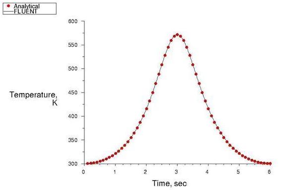
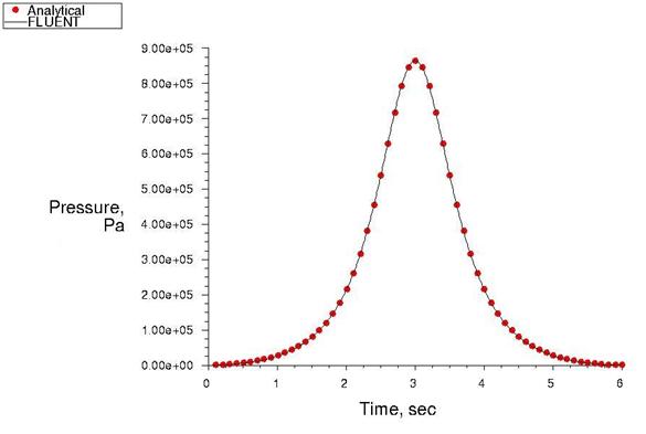
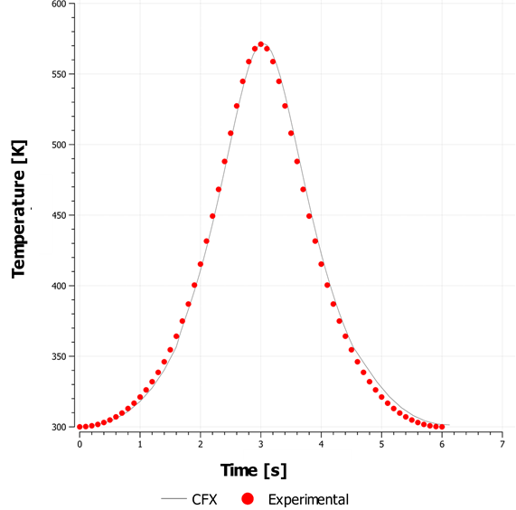
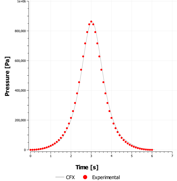
Air undergoes adiabatic compression due to the movement of a piston inside a rectangular box, representing a cylinder geometry in 2–D as shown in Figure 51: In-Cylinder Piston Description. The Top Dead Center (TDC) corresponds to a crank angle of 360°. The piston moves back after reaching TDC.


| Material Properties | Geometry | Boundary Conditions |
|---|---|---|
|
Ideal gas law for density Viscosity = 1.7894 X 10⁻⁵ kg/m-s |
Length of the block = 10 m Width of the block = 8 m |
Movement of the piston is modeled using deforming mesh |
Analysis Assumptions and Modeling Notes
The compression within the cylinder is assumed to be adiabatic. The spring-based smoothing method with local remeshing is used for modeling the dynamic mesh motion.