


Normally transformations you make (rotations, translations, zoom, scale) are performed globally. Global transformations affect the entire model as a unit and move all Frames, parts, and visible tools relative to the Global Axis. If the viewport is being viewed through a camera, the transformations move the camera. If the viewport is not viewed through a camera, the geometry is transformed. You can make the Global Axis triad (which pinpoints the Global Axis Origin) visible by selecting Axis Visibility → Axis - Global from View in the Main Menu.

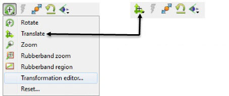
Most Global transformations you will make will be done interactively. Interactive Transformations normally affect only the single, selected viewport (the one which the mouse pointer is in when you click the left mouse button). The exception to this is if when you toggle on Link Interactive Transforms, causing the selected viewports in the Transformation Editor dialog to all transform together. You choose the type of transformation you wish to perform from among the Transformation Control icons.
Note: This icon changes to reflect the current selection.
- Rotate
When you choose Rotate, clicking the left mouse button and dragging horizontally will rotate the scene (including any tools that are visible) about the Global Y axis.
Clicking the left mouse button and dragging vertically will rotate the scene (including any tools that are visible) about the Global X axis.
Holding Ctrl down and then clicking the left mouse button and dragging will rotate the scene (including any tools that are visible) about the Global Screen Z Axis.
- Rotation Using Function Keys
Pressing the F1, F2, or F3 function keys will rotate the scene 45 degrees about the X, Y, or Z axis respectively. Holding Ctrl down while pressing these keys will rotate the scene by -45 degrees. The mouse must be located in the graphics window for these keys to work.
- Rotation Using Axis Triad
Moving the mouse over the model axis triad will display a rotation icon at the end of each axis. If the viewport where the axis triad is displayed is 3D, then pressing the mouse over one of these icons will rotate the view to look down the axis specified. If the viewport where the axis triad is displayed is 2D, then pressing the mouse over one of the rotation icons at the end of each axis will flip the direction you are looking from. Unlike the F1, F2, or F3 keys, the distance to the model and translates that may have been applied will not be reset.
- Translate
When this toggle is on, you can transform objects interactively in the Global X-Y plane (or by holding down Ctrl, in Z). Clicking the left mouse button and dragging will translate the scene (including any tools that are visible) up, down, left or right (or forward or backward).
- Zoom
A Zoom transform while in Global Tranform Mode is really an adjustment of the Look From Point, which you might also think of as the Camera Position. When this toggle is on, clicking and dragging to the left or down will zoom-in, that is it will move the Look From Point closer to the Look At Point. Clicking and dragging to the right or up will zoom-out, that is it will move the Look From Point farther away from the Look At Point. If you hold down Ctrl while interactively zooming, you will pan, i.e. move both the Look At and Look From Points in the direction of the mouse movement.
A Zoom transform while in Camera Mode is a movement of the camera in the camera Z direction.
As you Zoom in or out, be aware that you may clip the model with the Front or Back Z-Clip planes since they move in relationship to the Look From Point, always maintaining the distance from the Look From Point specified in the Transformation Editor dialog: Editor Function → Z-Clip.
- RubberBand Zoom
You specify the area of interest by clicking and dragging the white rectangle (rubber band) around the area you wish to zoom in on.
Band Zoom combines the functionality of a zoom-in transform as described above with a panning operation. The effect of performing a Band Zoom is that the area of interest that you specify will be centered in and will fill the selected viewport. EnSight adjusts the transformation center to be in the center of the area you specified.
The Transformation Editor is inactive for the Band Zoom Operation.
- RubberBand Region
You specify the area of interest by clicking and dragging the white rectangle (rubber band) around an area and the band zoom tool is located for you to blank out elements (click on the eraser) or to zoom (click on the magnifying glass), or to use this as a tool for other options.
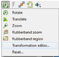
- Transformation Editor
For more precise editing options, choose Transformation Editor....
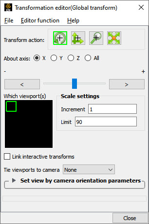
- Precise Rotation
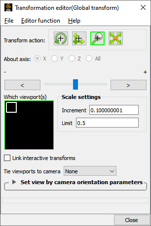
When the Transformation Editor is open under Global Transform (the title bar will show Global transform) and the Rotate toggle is selected, the dialog will be configured to permit precise Rotation.
Scale Toggle

Translate Toggle

Rotate Toggle

Zoom Toggle

You may rotate the entire scene or camera (including any tools that are visible) precisely about the X, Y, Z, or All axes by clicking on the appropriate axis of rotation toggle and:
entering the desired rotation in (+ or -) degrees in the Increment field and pressing Enter,
clicking the stepper buttons at each end of the slider bar (each click will rotate the model by the number of degrees specified in the Increment field), or
dragging the slider in the positive or negative direction to the desired number of degrees you wish to rotate the model (the Limit Field specifies the maximum number of degrees of rotation performed when the slider is pulled to either end of the slider bar).
- Precise Translation
When the Transformation Editor is open under Global Transform and the Translate toggle is selected, the dialog will be configured to permit precise Translation.
You may translate the entire scene or camera (including any tools that are visible) precisely along the X, Y, Z, or All axes by clicking on the appropriate direction toggle and:
entering the desired translation in (+ or -) model coordinate units in the Increment field and pressing Enter, then
clicking the stepper buttons at each end of the slider bar (each click will translate the model by the number of model coordinate units specified in the Increment field), or
dragging the slider in the positive or negative direction to the desired number of model coordinate units you wish to translate the model and then releasing the slider (the Limit Field specifies the maximum number of model coordinate units that the model is translated when the slider is pulled to either end of the slider bar).
- Precise Zooming
When the Transformation Editor is open under Global Transform and the Zoom toggle is selected, the dialog will be configured to permit precise Zoom.
You may precisely adjust the position of the Look From Point (with respect to the Look At Point) or move the camera in the camera Z-direction by:
entering in the Increment field the desired modification (+ or -) in the distance between the two Points (a value of .5 will increase the distance to be equal to 1.5 the current distance, a value of 1.0 will double the current distance), then
clicking the stepper buttons at each end of the slider bar (each click will increase or decrease the distance between the two Points by the factor specified in the Increment field), or
dragging the slider in the positive or negative direction to the desired modification factor and then releasing the slider (the Limit Field specifies the maximum modification factor for the distance between the two Points when the slider is pulled to either end of the slider bar).
- Precise Scaling
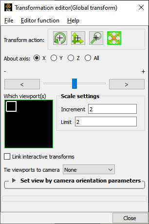
Interactive modifications to scale are not permitted. When the Transformation Editor is open under Global Transform and the Scale toggle is selected, the dialog will be configured to permit precise adjustments to the scale of the scene. If in Global Transform Mode the scene will be scaled. If in Camera Transform Mode the size of the camera glyph will be changed.
You may precisely rescale the scene or camera in the X, Y, Z, or All axes by clicking on the appropriate scaling direction and:
entering in the Increment Field the desired rescale factor and pressing Enter (A value of .5 will reduce the scale of the scene in the chosen axis by half. A value of 2 will double the scale in the chosen axis. Be aware that entering a negative number will invert the model coordinates in the chosen axis. ), then
clicking the stepper buttons at each end of the slider bar (Clicking the left stepper button will apply 1/Increment value to the scale. Clicking the right stepper button will apply the entire Increment value to the scale), or
dragging the slider in the positive or negative direction to the desired scale factor and then releasing the slider. (Dragging the slider to the leftmost position will apply 1/Limit value to the scale. Dragging the slider to the rightmost position will apply the entire Limit value to the scale).
- Link Interactive Transforms
If you have multiple viewports you may link them together such that interactive (those performed in the graphics window) transformation that occurs in one of the linked viewports occurs in the other linked viewports. To link the viewports select all of the viewports to be linked in the Which viewport(s) window and turn on the button. An L will occur in the viewport outlines in the Which viewport(s) window indicating which viewports are linked.
- Tie viewport(s) to camera
A viewport may either be in Global Transform Mode or in Camera Mode. In camera mode the viewport is viewed through a camera. This pulldown makes this choice.
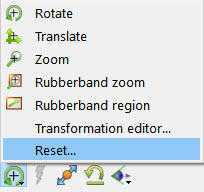
- Reset...
Clicking the and button in the Transformation Control Area will open the Reset Tools and Viewport(s) dialog.
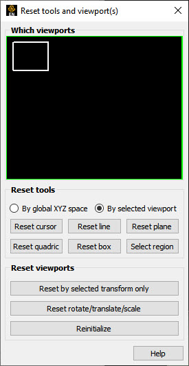
- By Global XYZ Space Toggle
When enabled, clicking a button will cause the Cursor, Line, Plane, or Quadric Tool to reset to its initial default position.
- By Selected Viewport Toggle
When enabled, clicking a button will cause the Cursor, Line, Plane, or Quadric Tool to be repositioned in the center of the geometry for the selected viewport.
- Reset Cursor
Clicking this button will cause the Cursor Tool to reset according to the By toggle.
- Reset Line
Clicking this button will cause the Line Tool to reset according to the By toggle.
- Reset Plane
Clicking this button will cause the Plane Tool to reset according to the By toggle.
- Reset Quadric
Clicking this button will cause the currently selected Quadric Tool to reset according to the By toggle.
- Reset Box
Clicking this button will cause the Box Tool to reset according to the By toggle.
- Reset Select region
Clicking this button will cause the Selection Tool to reset according to the By toggle.
- Reset By Selected Transform Only
Clicking this button will cause the transformation selected in the Transformation Control Area to reset for the viewports selected in the dialog's Viewport(s) area.
- Reset Rotate/Translate/Scale
Clicking this button will cause the rotate, translate, and scale transformations to reset for the viewports selected in the dialog's Viewport(s) area.
- Reinitialize
Clicking this button will cause the viewports selected in the dialog's Viewport(s) area to reset and recenter on the Parts which are visible in the Viewport(s).
- Reset using Function Keys
Pressing the F5 button will change the scene in the current viewport to the standard right side view. Similarly, pressing F6 will show a top view and F7 a front view. Pressing F8 will restore the view to the one which existed before F5, F6, or F7 were pressed. If Ctrl is pressed at the same time as F5, F6, or F7, then the current view will be stored to the selected button.
To provide compatibility with other post processors, EnSight provides the ability to set the global transform for the selected viewports according to camera view settings specified. The view parameters are not updated as the user interacts – they are merely used to set a specific view.
Import Parameters From File...
Opens a file browser where the user can choose either a .gsav view file created by Ansys Mechanical or a EnSight view file described in Global View File Format. If the selected file is valid, the view is set according to the parameters given and the input fields in the dialog are populated.
View Direction
Specifies the view direction.
Focal Point
Specifies a focal point for the view.
Distance to Focal Point
When used with the focal point and view direction will compute the location for the viewer (For example, camera location).
Rotation Angle
The angle (in degrees) to rotate the view about the view direction axis.
Compute View
Will set the global transformation for the selected viewports according to the defined parameters.