


The following topics are included in this section:
Sometimes you may wish to output geometric data or variable values from EnSight to be included in a different analysis code, or to be used in a presentation. EnSight has internal writers as well as external, user-defined writers, which use the EnSight writer API (available to any EnSight user).
EnSight has several internal writers that allow saving geometric data and variable values:
Brick of Values (used for volume rendering of variables for 3D Parts only)
Case (EnSight Gold)
Simple Client Output
PLY Polygonal File Format
GLTF File Format
AVZ
In addition to these internal writers, EnSight also has four user-defined writers that each use the EnSight user-defined writer API. Each user-defined writer must be compiled into a dynamic shared library that is loaded at runtime and listed in the Save Geometric Entities dialog with the internal writer formats.
Both internal and user-defined writers have access only to the geometry of selected parts and active variables. The Simple Client Output, PLY Polygonal File Format, GLTF File Format and AVZ writers save geometry and variable values only on the client. The remaining writers save only parts located on the server and all active variables. Server parts include all original model parts, and the following created parts: 2D-clips, Elevated Surfaces, Developed Surfaces, and Isosurfaces.
Note: That element filtering is ignored when saving out server parts; element filtering is only used for GLTF export. Client parts include the surface elements available on the client.
Simple Client
The Simple Client Output internal writer tessellates the elements on the client into triangles and saves the tessellated elements of the selected part(s) into an ASCII or binary file containing first a list of the x, y, z coordinates followed by the connectivity triplets, followed by the variable values of each of the selected, active nodal variables at each of the coordinates.
Note: This format does not support the saving of per-element variables.
PLY
The PLY Polygonal File Format internal writer tessellates the elements on the client into triangles and saves the tessellated elements of the selected part(s) into an ASCII or binary file containing first a list of the x, y, z coordinates with their respective color in RGB format, followed by the connectivity triplets. This format does not save variable values, but merely color at each node in RGB format.
GLTF
GLTF (GL Transmission Format) is a specification for the efficient transmission and loading of 3D models on the web. It minimizes both the size of 3D assets, and the runtime processing needed to unpack and use those assets. It defines an extensible, common publishing format for 3D content.
The EnSight GLTF internal writer saves all the selected parts on the client in their current visible state into triangle meshes and lines (points are discarded). EnSight saves into GLTF 2.0 format (.gltf, .bin, or .glb) on the client. Two file modes are supported: text and binary. The text mode will generate two files: a .gltf file, which is an ASCII scenegraph file, and a .bin file, which is a binary data file. The binary mode will generate only one binary .glb file, which contains everything.
When exporting transient data, if Save as a single file is unchecked, each time step will be written to a separate file with the time step number appended to each output file name. If it is checked, all time steps will be written to one file.
GLTF Limitations
GLTF does not support volume rendering therefore, none of the parts can be rendered in Volume element representation. The GLTF format supports nodal variable coloring only. Parts colored using element variables will be interpolated into nodal variables automatically. The GLTF format does not support thick line width. Line width will always be 1. The GLTF format does not support EnSight's own color by modes of limit fringe, display undefined values, etc. The GLTF format does not support alpha by a variable. The GLTF format does not support surface flow texture.
The user-defined writers can call the routines of an EnSight API to retrieve, to get, for example, server side nodal coordinates, connectivities, node ids, and element ids of parts as well as active variable values on those parts selected in the Parts window to be passed by value to be used, manipulated and/or written out in any format desired. User-defined writer dialog includes a Parameter field that allows passing in a text field into the writer from the graphical user interface for extra options. Normally the active variables are all saved, but the following command tells the user defined writers to save only the selected variables:
test: write selected vars
Several example user-defined writers (including source code header files, Makefile and the corresponding shared library) are included to demonstrate this capability.
The Case (Gold) Lite writer is included to demonstrate how to exercise most of the API and output a subset of the Case (Gold) format. Complex numbers and custom Gold format are not supported with this writer. While the writer is not compiled, the source code of this writer, the required header files, and the Makefile are included.
The Flatfile user-defined writer outputs
coordinates and active variables (scalar and/or vector only) for all selected parts. The
format is ASCII comma delimited so it is easily imported into other applications. If any of
the keywords ANSYS or force or
body is entered into the Parameter field, then
Flatfile will output an Ansys body force file. If NODEID or
nodeid is entered into the Parameter field then node ids are
written out. If SSCALE # is entered in the parameter field then
scalar variables will be scaled by the float value (for example SSCALE
3.1415 will multiply every value of the scalar by 3.1415). Similarly,
VSCALE # will scale each component of a vector variable and
GSCALE # will scale each value of the nodal coordinates. Only
active nodal variables are exported unless CELLID is entered into the
Parameter field, and then only active element variables are written
out for each element id, including the element id (if it exists).
The STL user-defined writer is designed to write out the border geometry in the form of triangular 2D elements of the selected part(s) at the beginning timestep. The end time and the step time are ignored. The STL format does not support multiple parts in a single binary file, but does support multiple parts in a single ASCII file. Therefore, if multiple parts are selected and ASCII is checked, the STL writer outputs an ASCII file with the border of each of the parts. If multiple parts are selected and binary is checked, the STL writer outputs a binary file containing a single border of the multiple parts.
The Dynamic Visualization Store writer exports the currently selected parts and the active variables to DVS format. The binary option, single file format and parameter field are all ignored. This writer currently does not support structured parts, tensor and complex variables. Such objects are skipped during the export operation.
Finally a user-defined writer is available for the Exodus II data format.
More user-defined writers may be distributed with EnSight in the future.
AVZ
AVZ is a format developed by Ansys for the display of 3D geometry in a web page or the stand alone AnsysViewer. All data, including transient, will be written to a single file with the .avz extension. For more information on the .avz extension, see Ansys Viewer User's Guide.
All parts are exported, with visibility status preserved
Supports transient export, with some limitations described below
Preserves part structure
Exports legends, preserving coloring, number of levels, and smooth/banded
Constant color, per node, and per element variable coloring are all supported
Supports both fully opacity and constant transparency
Mirror symmetry is preserved
Displacements are preserved
AVZ Limitations
Rotational and translational symmetry are not supported
Background color is not exported
Element outlines, enabled by 'Overlay hidden lines', are not supported
When playing transient data, all parts will be shown, even the parts that were hidden during export
Alpha by a second variable is not supported
Volume rendering and surface opacity by variable are not supported
Rigid body motion is not preserved
Text Annotations are not exported
Flipbooks are not supported
Keyframe animations are not supported
Plotter and Queries are not supported
Multiple EnSight Viewports are not exported
LIC/Surface Flow Texture is not supported
Animated Particle Traces are not supported
The Time value in the AVZ slider does not correspond to the analysis simulation time
Smoothing Per Element variables display is not supported by AVZ
Lights and materials are not exported
Figure 2.18: Save Geometric Entities Dialog (Showing Case (Gold) Internal Writer, and STL External Writer)
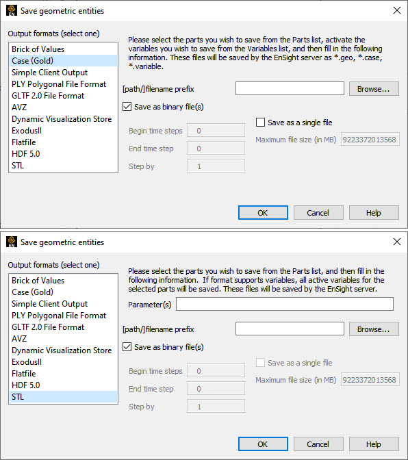
The Save Geometric Entities dialog is used to save Selected Model, 2D-Clip, Isosurface, Elevated Surface, and Developed Surface Parts as EnSight Case (Gold) files. Therefore modified model Parts and certain classes of created Parts can become model Parts of a new dataset.
File → Export → Save Geometric Entities...
Output Format
Specify the desired format: Brick of Values, Case(EnSight Gold), Exodus, Flatfile, STL, and possibly other user defined writers.
Parameter
Allows passing a text field from the graphical interface to the writer for extra options. Some writers make use of this field to modify their behavior (see Flatfile, for example) while others ignore this field. See the README file(s) in the following directory $CEI/ensight242/src/writers.
[path]/filename prefix
Specify path and filename prefix name for the saved files. For Case(Gold), the saved geometry file will be named filename.geo, the casefile will be filename.case, and the active variables will be filename.variablename. The other writers will vary.
Save as Binary File(s)
Save as Binary File(s) specifies whether to save the data in ASCII (button toggled off - default) or binary (button toggled on) format. Writers vary in their handling of this.
Note: The GLTF exporter will use .gltf suffix for the text output and .glb for the binary file.
Begin Time Step
Begin Time Step field specifies the initial time step for which information will be available to save for all selected Parts and activated variables. Writers may vary in their usage of this information.
End Time Step
End Time Step field specifies the final time step for which information will be saved for all selected Parts and activated variables. Writers may vary in their handling of this.
Step By
Step By field specifies the time step increment for which information will be saved for all selected Parts and activated variables starting with Begin Time Step and finishing with End Time Step. The Step By value MUST be an integer. Writers may vary in their handling of this.
Save as a Single File
Toggle on to have a single file per variable - containing all values for all time steps for that variable. The default is to have a file per variable per time step. Writers may vary in their handling of this.
Maximum File Size
For Single File option, can specify the maximum file size. Continuation files are created if the file size would exceed this maximum. Writers may vary in their handling of this.
OK
Click to pass the graphical user interface values to the selected writer, and begin executing the writer routine
Since EnSight does something special with the model timeset when rigid
body information is read (via the rigid_body option in the casefile, or
from a user-defined reader with rigid_body reading capability), you need to
be aware of a few important issues. EnSight assumes that the rigid body timeset encompasses
the normal geometry timeset, and it replaces the normal geometry timeset with the rigid body
timeset - therefore the following occurs when using this option.
If any created parts are in the list to be saved, EnSight will save as true changing coordinates. Namely, a geometry file containing the coordinates for each part will be saved at each time. Upon re-reading this model, you will be able to duplicate all actions, but it will be done as a true changing coordinate model. In other words, the original rigid_body file nature will not be duplicated.
If the original model had static geometry and rigid body file information - and you do not have any created parts in the list to be saved - saving will preserve the single static geometry and rigid_body file nature of the model. However, if the original model had changing geometry, or if variables have been activated - the number of geometry/variable files saved will be according to the rigid body timeset. This timeset often has many more steps than the original timesets - so be wise about the number of steps you write. It is often important to use the Step by option to control this.
Because of the things mentioned in 1 and 2 above - if you want to use the save geometric entities option in EnSight to translate a rigid body model from a different format into the EnSight format, you may want to consider the following process. First, read in the model without the rigid body transformations, activate the desired variables, and save the model. Second, read in the model with the rigid body transformations, do not activate any variables, and save the model (with a different name). Edit the Casefile of the first model to use the model: and rigid_body: lines of the second casefile instead of the first casefile.
Export of Other formats
EnSight also supports the export of a number of other formats. See the File import/export folder in the User Defined Tools icon.
| Problem | Probable Causes | Solutions |
|---|---|---|
|
A Part was not saved |
User attempted to save an unsupported Part type. |
Select only Model, Isosurface, 2D-Clip, and Elevated Surface Parts. |
|
Variable(s) not saved |
The variable was not activated or the variable was a constant. |
Activate all scalar and vector variables you want saved. |
| Error saving | File prefix indicates a directory that is not writable or disk is out of space. |
Re-specify a writable directory and valid prefix name. Remove unneeded files. |
|
My custom user-defined writer doesn't show up on list of formats |
Didn't load at startup |
Start EnSight with EnSight loads user-defined writers at startup from shared libraries found in $CEI/ensight242/machines/$CEI_ARCH/lib_writers If your user-defined writer is not in the default directory, tell EnSight where to find it by: |
|
setenv ENSIGHT10_UDW location |