To trace particles through a steady-state flow field (streamline):
Select the flow field mesh part(s) to trace through.
Click the Particle Traces icon.

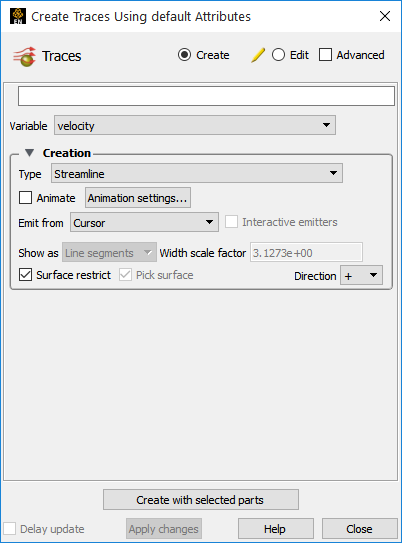
Select the vector variable to use.
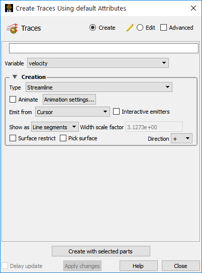
Select Streamline as the type.
Select the desired emitter.
If the emitter is a tool (Cursor, Line, Plane), position the tool at the desired emitter location. If the chosen emitter is Part, then enter the part number in the Part ID field and press Return.
Click to set the trace direction:
+: forwards in time (positive velocity direction) from the emission point(s).
-: backwards in time (negative velocity direction) from the emission point(s) towards the entering flow boundary (Streamlines only).
+/-: both forwards and backwards (Streamlines only).
Click buttons.
The particle traces will be created from the desired emitter. Their maximum time duration is controlled via the Total Time Limit found under the Emitter Information when Advanced is chosen instead of Simple.
See Use the Cursor (Point) Tool, Use the Line Tool, Use the Plane Tool.
The following are the available Emit From options:
Note: Traces will only be generated for those emitter points that actually lie within an element of the selected flow field part(s).
|
Cursor |
A single trace will be emitted from the Cursor tool. |
|
Line |
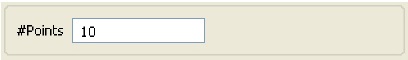
Multiple traces will be emitted from evenly spaced points along the Line tool. Enter the desired number of traces in the # Points field and press return.
 |
|
Plane |
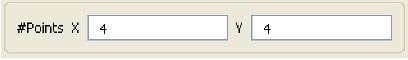
Multiple traces will be emitted from evenly spaced points in a grid pattern over the Plane tool. Enter the desired number of traces in the X and Y direction (with respect to the Plane tool's axis) in the # Points X/Y fields and press return. The total number of traces will be the product of X and Y.
 |
|
Part |
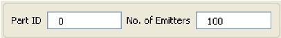
One trace will be emitted from the number of nodes of the part you specify. This number of nodes will be randomly selected. Enter the Part ID number (from the main Parts list) of the part you wish to use as an emitter, and the number of nodes. Limitation: if you create a particle trace from a Part ID, you cannot later change the ID nor can you change the emitter type to something else (such as Cursor).
 |
|
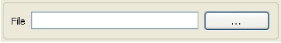
File |
Traces will be emitted from the locations, and at the times, specified in an EnSight Particle Emitter file. See EnSight Particle Emitter File Format.
 |
To Quickly Create a Particle Trace
Select the parent part(s).
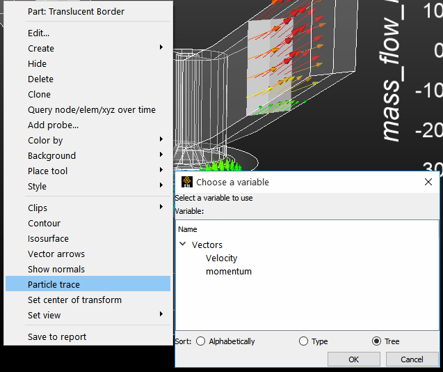
Right click on a tool (cursor, line or plane).
Choose .
If you have no parts selected then a dialog will pop up to ask you to select part(s).
If there are more than one vector variables, then a pop up will ask you to choose your vector variable.
This will create streamline trace(s) using default settings and the tool as the emitter.
The complete set of particle trace can be edited in the Create/edit dialog for Traces, when in Advanced mode. For example, the emitter can be changed under the Emitter Information in the Creation section:
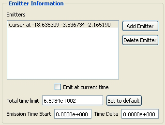
Toggle on to have start time be the current time, otherwise specify the start time (Streamlines only).
Total time limit sets the total amount of time a trace will last (it may terminate for other reasons as well). An intelligent default will be set for you.
Emission Time Start is the solution time at which to begin pathline trace (Pathlines only).
Time Delta emission time for pathlines.
If not zero, a new set of traces will be emitted at S, S+D, S+2D, etc. into the changing flow field (where S is the Start time and D is the delta value). Used to create streaklines or smoke traces. Animated streaklines are one of the most powerful methods for visualizing transient flow (Pathlines only)
Streamline and Pathline Particle paths can be displayed as lines, ribbons, tubes or square tubes, where ribbon or tube twist follows the local flow rotation. To enable ribbon or tube display, and change trace arrowheads:
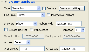
Double-click the desired particle trace part in the Parts list (or right click on it in the list or in the graphics window and select ). This will open the Create/edit Parts dialog. If necessary, toggle on Advanced mode, and open the Creation section.
Set Show As to Ribbon, Tubes or Square Tubes.
If desired, change the default ribbon or tube width and press Return.
Select the Arrowhead representation desired. (Cone, Normal, or Triangles)
Set the # of arrows to display along a trace.
Set the Arrow size.
Note: Node tracks and min/max variable tracks can only be displayed as lines. Trace arrowheads can be used for tracks, but this must be done from the Particle Trace Feature Panel.
Any type of particle trace can be animated. See Animate Particle Traces for more information.
Each individual particle trace visibility status and color can be controlled via a right mouse button selection of the particle trace in the graphics window.
Note: Coloring individual traces only works if the trace part is a constant color.
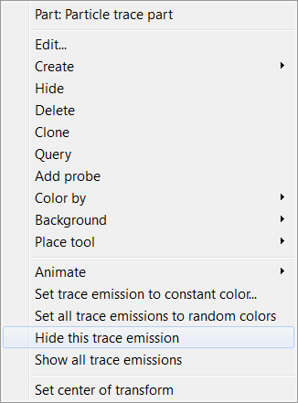
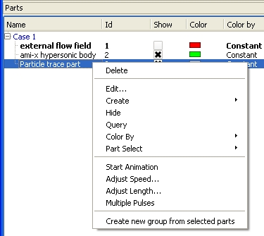
Right click on an individual trace to see the following menu:
If the particle trace part is colored by a constant color (this will not work if the particle trace is colored by a variable).
Select to choose a color to set the selected emission. The standard color widget will appear to allow you to select a color.
Select and EnSight will automatically assign a random color to each emission of the particle trace part.
To clear the per trace color simply color the part by a constant color (see Change Color).
Each individual trace can be turned invisible by selecting .
Reset all traces to visible using .
Rather than emit from a tool or a part, you can also interactively pick points on a surface in the Graphics Window to define emitter locations. To do this:
Select the flow field mesh part to trace through.
Click the Particle Traces icon.
Toggle on .

Click .
And the following dialog will appear:
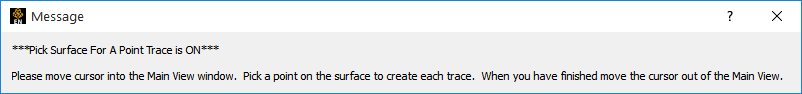
Do as instructed, move the mouse into the Graphics Window and click the left mouse button when the cursor is over the desired location. The clicked point must be found within some element of the selected 3D part to result in a trace.
You can click to create as many point emitters as you like. When done, move the mouse out of the Graphics Window.
Click off .
Note: You can also specify a rake (line) or net (plane) emitter by picking on a surface. Just set the emitter to Line or Plane prior to clicking . Then follow in the instructions in the pop-up window.
EnSight can trace particles such that they are constrained to lie on a (not necessarily planar) 2D surface even if the velocity is zero at the surface. The trace is calculated by projecting a short distance off the surface into the 3D flow field and using the velocity value found there. Both the projection distance (variable offset) and a display offset are user definable and are in the surface normal direction.
Surface-restricted trace emitters are defined by mouse action in the Graphics Window. When you click and drag over the desired surface, the emitter is defined by projecting the mouse path onto the surface. To trace surface-restricted particle traces:
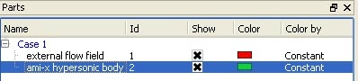
Select the desired surface part(s) in the Parts list. This should be the surface you wish to trace on.
Click the Particle Traces icon.
Set the desired vector Variable to use for tracing.
Select the desired emitter type (Cursor, Line, or Plane).
Note: The applicable tool will not actually be used in this operation (a pick action will be used).
Toggle on the button.
Note: All subsequent tracing will be assumed to be surface restricted until this is toggled off.
If the Emit From is set to Line or Plane, enter the desired number of points (Line) or X and Y points (Plane).
Click the Create with selected parts button.
Move the mouse pointer into the Graphics Window and:
for a Cursor emitter: click the left mouse button on the desired location.
for a Line emitter: click and hold the left mouse button on one endpoint of the desired line. Drag to the other endpoint (a white line will provide feedback).
for a Plane emitter: click and hold the left mouse button on one corner of the desired region. Drag to the opposite corner (a white rectangle will provide feedback).
You can continue to specify emitters of the selected type as long as the mouse pointer remains in the Graphics Window. When the pointer exits the window, the trace part will be created.
When done, toggle off both , and then .
Note: In Advanced mode, you have control over the various other of the trace - including variable offset, display offset, trace direction, etc.
If a particle trace was created from one of the tool emitters (Cursor, Line, or Plane) and the trace is a streamline trace, the emitter can be made interactive. When interactive, the tool that created the particle trace part can be moved with the mouse. As the tool is moved, new particle traces are automatically recalculated and redisplayed (This option is not available for surface-restricted Particle traces, traces emitted from a Part, in Server of Server mode, or to Pathlines). To trace interactively:
Either create a particle trace part as described above (based on a tool) or double-click an existing particle trace part to open the Parts Feature Panel, and turndown the Creation.
Toggle on Interactive Emitter.
If the tool that originally defined the emitter is not visible, it will be turned on by this operation.
Move the mouse into the Graphics Window and manipulate the tool as desired. See the article on the applicable tool for information on tool manipulation ( Cursor, Line, or Plane).
When done, toggle off Interactive Emitters.
EnSight provides complete control over transient particle tracing. Both the start time and the stop time can be specified. In addition, you can specify a delta value for an emitter that will cause additional particles to be emitted into the flow at regular intervals. This type of pathline is also called a streakline or smoke trace.
You create a pathline trace by setting the Type to Pathline (rather than Streamline) prior to clicking Create. By default, the pathlines will start at the first time step of your simulation and terminate at the last step (unless stopped earlier). You can change these defaults within the Emitter Information in the Creation section of the Create/edit dialog as described above.
Complete control over all creation attributes is found in the Advanced mode of the Create/edit Parts dialog for particle trace parts. There are many ways to get to these. Some are:
Double click on the desired Particle trace part in the Parts list
OR
select the desired Particle trace part in the Parts list and click the Particle traces icon.
OR
right click on the desired Particle trace part in the Parts list and select
OR
select → , then select the desired Particle trace part in the Parts list.
Make sure you are in mode.
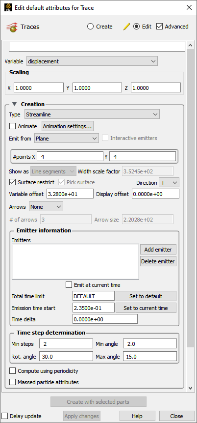
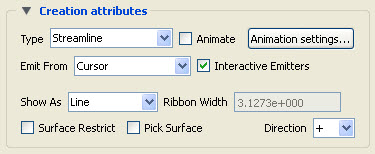
Variable sets the desired flow field variable.
Type sets the trace type
Interactive emitter sets interactive emitter.
#Points X Y sets the number of points (If Line or Plane emitter are selected).
Show as displays Line segments, Ribbons, Square Tubes or Tubes.
Ribbon width sets the ribbon width.
Surface restrict toggles on Surface Restricted tracing.
Variable offset sets surface restricted variable and display offsets.
Pick surface toggles on surface picking for emitter definition.
# of arrows displays the number of arrows alone the trace.
Arrow size sets Arrowhead size.
Emitters displays the list of the emitters belonging to the selected trace part.
adds a new emitter to the selected part based on the current.
deletes the selected emitter.
Toggle on to emit at current time or set emission time.
Total time limit sets emitter total time.
Emission time start sets emission start and delta.
Set to default sets Total Time to the default.
EnSight also provides massed particle traces via the Advanced mode in the Feature Panel for Traces.
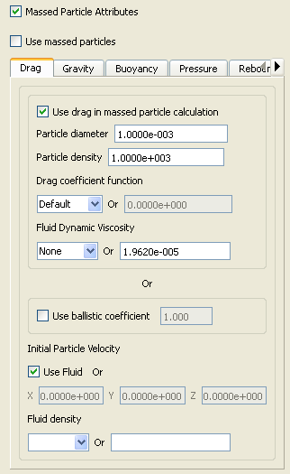
Open the Parts Feature Panel for the desired particle trace part by one of the several methods shown above.
Click the toggle to reveal the massed particle parameters.
Modify the massed particle parameters according to your dataset.
Each term in the momentum balance equation has a separate tab containing the parameters which pertain.
Toggle on .
The selected particle trace part will update to a massed particle trace(s) taking into consideration the parameters you specified.
For the theory used in massed particle traces, see Particle Trace Parts.
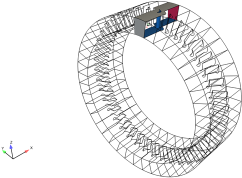
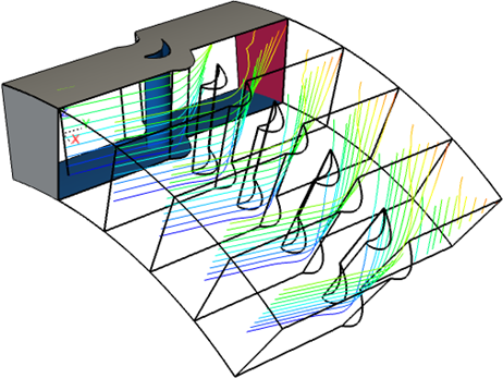
EnSight also provides a special option for rotational periodic geometry. Both streamlines and pathlines, which exit a symmetry face of a part, can re-enter the part at the corresponding symmetry face and continue. As will be illustrated below, one must first specify the correct symmetry for the periodic geometric parts, and toggle on the periodic option.
See below for an example model of the flow field and surfaces of an axial blade with angled inlet - periodic faces are set as non-visual and, the top view has the original and all of the remaining 40 instances, while the bottom view has the original as well as four instances as shown below:
Select the periodic field parts that share the same symmetry attributes. In this case, the field part is the Blade Region.
Place your emitter tool in the original instance prior to making instances.
Important: You cannot emit within the symmetry instances as they are graphical only.
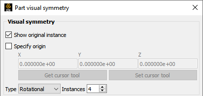
Click the Visual Symmetry icon to open up the Part Visual Symmetry dialog.

Choose Rotational symmetry, the Axis of rotation (here X), set the number of Instances for full 360 degree rotation (in this case
41).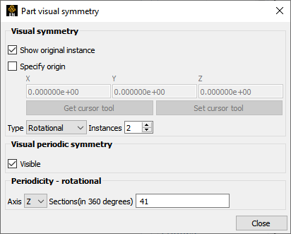
Note: In this case, each slice is 360/41 degrees.
Toggle Axis to show the original instance, and the number of instances to show (in this case shown below, show
4).If you show the original instance, then
40will show the entire 360 rotation. If not showing the original instance then41will show all.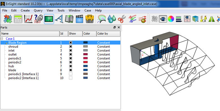
Click on the Particle Traces icon, to open the Create Traces dialog and click the toggle – to open the full dialog.
Set your desired options as explained in other sections of this How To (streamline or pathline, emit from, etc.).
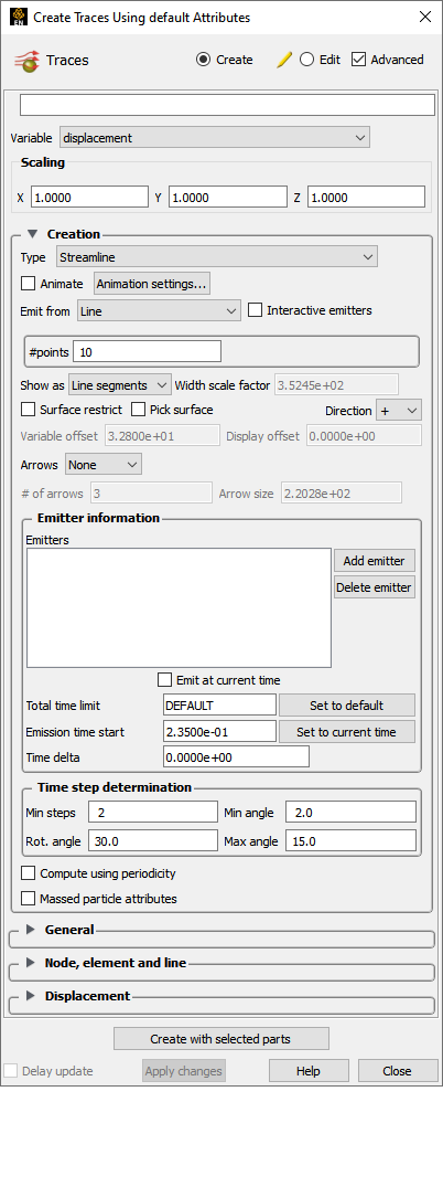
Toggle on .
Note: This will use the information from the parent Visual symmetry dialog.
Click the button. If you only have one instance of the parent flow field part showing, streamlines will be shown entering and exiting the flow field part and can be confusing. It is helpful to display several instances in the visual symmetry dialog.
With the newly created particle trace part selected, click on the Visual symmetry icon.
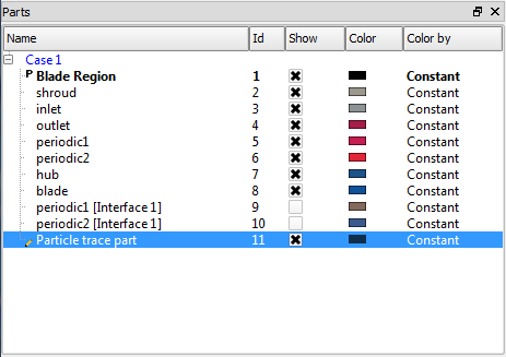
In the resulting Part Visual Symmetry dialog, choose Rotational symmetry.
Show the same number of instances of the particle trace part as the parent flow field part. Turning on Visual Periodic Symmetry with multiple parent instances will give you a sense of the flow between the instances as shown below.
EnSight provides the capability to track the location of node(s) through time. As one would expect, node ids are required, and this only makes sense for nodes that change location over time - whether by changing geometry or by transient displacement. Measured particle parts are often a particularly good choice for this option.
Select the part(s) containing the nodes you wish to track in the Part list.
Click on the Particle Traces icon.
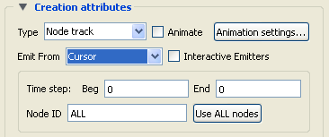
Set Type to Node track.
Optionally you can modify the Beg (begin) and End (end) times to use for the track. The default will be all time steps.
Specify the particular Node ID you wish to track, or do ALL.
You can use the button to select all if you have modified the field.
EnSight provides the capability to track the location of the minimum or maximum of a chosen variable through time. This of course only makes sense for transient models.
Select the part(s) containing the variable, for which you wish to track the min or max.
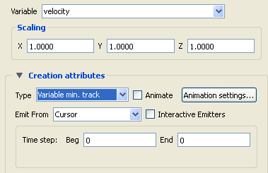
Set Type to Variable min. track (Or Variable max. track).
Select the desired Variable.
Optionally you can modify the Beg (begin) and End (end) times to use for the track. The default will be all time steps.
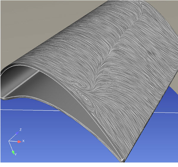
EnSight provides the capability to visualize the flow over a surface part, similar to tufts in a wind tunnel. This visualization is not interactive, nor is it animated; it is a graphical texture of the flow tufts calculated on the part surface using surface velocity (or velocity in the flow just above the surface) using the Line Integral Convolution algorithm. It is designed to provide a uniform visualization of the flow of a vector over a surface. This will update when time is changed for transient data. See Surface Flow Display for details.