


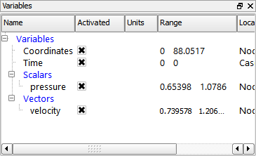
Unlike the dataset used in the previous chapter, this data contains two variables: pressure and velocity. The first step is to color the model by the pressure variable and display a color legend showing the mapping from variable values to color.
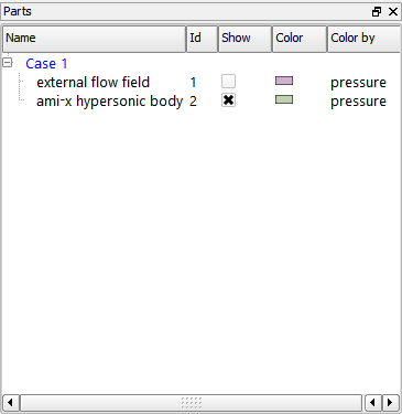
Select the ami-x hypersonic body part in the Parts list.
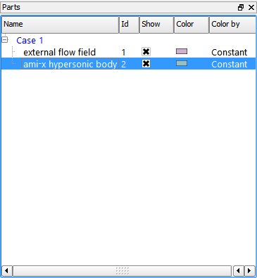
Toggle off the Highlight Parts When Selected toggle to turn off part selection highlighting.

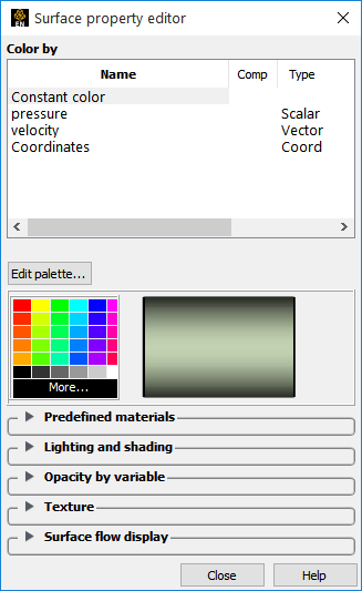
Click the Color/Surface Property icon in the Quick Action Icon Bar to open the Color editor.

Select the pressure variable in the Color by list.
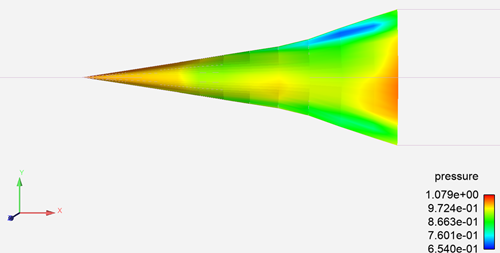
The color legend appears to the right of the model in the Graphics Window (default behavior - this is a user-controllable preference).
Note: The display of legends can be controlled by right-clicking on the proper Legend in the Annotations object list.
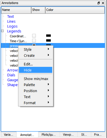
We won’t actually modify the legend visibility at this time. Also note that color legends have many display attributes – see Create Color Legends ( → ) for more information.
Click the X to close the dialog.
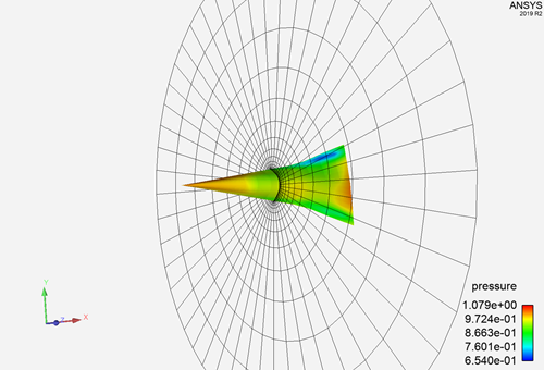
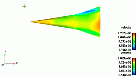
Your Graphics Window should now appear similar to the following:
There are several other ways to color a part by a variable. If your hardware is properly set up you can use drag and drop.
See Create Color Legends for more information.
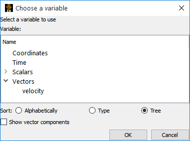
In the Variables list, open the Vectors group to find Velocity.
Click with the left mouse button on Velocity and keep the mouse button pressed while you drag the mouse into the background of the graphics window.
Release the left mouse button. This will now color all parts in the viewport by Velocity, as well as change the legend.
Open the Scalars group and drag and drop pressure into the graphics window.
Clipping Plane Part
In the next sequence of operations, we will create a new part: an X clip.
Once the clipping plane has been created, we will build a contour part using the clipping plane as the parent part.
Like many things in EnSight there are several ways to perform the X clip operation. We will take advantage of the right click capability. In the Parts list right-click on the external flow field part.
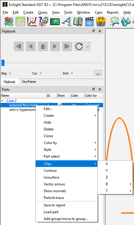
Select Clips, then X to create an X clip through the part you right clicked on at the default position, that is, the mid point in the X direction.
Note: A new part Clip_plane is now listed in the Parts list. There is also a new part in the Graphics Window but you cannot see it since it is perfectly parallel to our line of sight: rotate the model to see the clipping plane. See Create Clips (Help → How to manual...) for more info.
Move the mouse pointer into the Graphics Window, click and hold the left mouse button and drag to rotate the model. Similarly, you may want to zoom the model by dragging the right mouse button (or rotating the mouse wheel) in the Graphics Window.
It might be better if the clip plane was not shaded so we could see the model through it.
If the Quick Action Icon Bar is not currently showing part icons (that is, the toolbar is showing the first icon to be a puzzle piece), click on the Clip_plane part in the Parts list. Then click the Shaded icon in the Quick Action Icon Bar.

Depending on how you rotated and zoomed, you should now see something like the following in the Graphics window.
See Create Clips.
The new Clip_plane part listed in the Parts list has attributes just like the original model parts. For example, we can color the part based on the value of a variable and change other attributes as well (like we just did with its visibility).
Click the Color icon in the Part Quick Action Icon Bar.
Select velocity in the Variables list and then close the dialog.
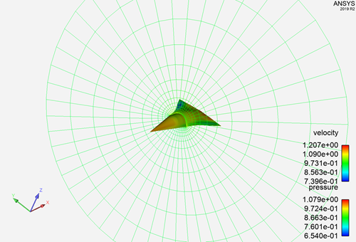
Your Graphics Window display should look something like the following:
A quick way to color a part is to right-click it and select → in the resulting popup.
In the popup window, select Velocity and click . The clip plane is colored by Velocity.
Or click and drag the variable out from the Variables list and drop it on the part in the graphics window.
The following should be kept in mind when creating new parts in EnSight:
A new part is created from one or more parent parts. You must select these parts either in the Part list or by selecting them in the graphics window. If you use right click the selection is performed during the right click operation.
A part creation type is selected - either from right click, selecting the feature from the Secondary Feature bar, or selecting it from the Create pulldown.
The new part is created either directly or through the Feature Panel after possibly modifying the creation attributes.
Any desired attributes - visual or creation - are modified for the new part.
Contour Part
The clip plane was built using the external flow field as the parent part. Since the clip plane is itself a part, it can be used as a parent part to create other parts. To create contour loops of velocity on the clip plane, for example.
The Clip plane was created using right-click capability. We could to the same for the contours, that is, right-click on the Clip_plane part and use the Contour function in the pulldown list. But here we build the part through the user interface so you can see how this is done.
Select the Clip_plane part in the Parts list.
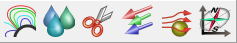
Click the Contour icon in the Feature Icon Bar to open the Feature Panel for Contours.
Select Velocity in the Variables list.
Change the value of the Sublevels field to
3.Click Create with selected parts to build the new contour part.
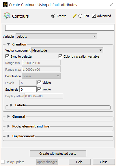
By default the Sync To Palette toggle is activated so that EnSight creates a contour loop at each level in the color palette assigned to the selected variable. Levels are evenly spaced values that span from the minimum to the maximum range of the variable. Default color palettes have five levels. The subcontour value sets the number of additional contour loops that will be calculated between each level. In this case, 17 total contours will be calculated: ((5–1)*3)+5.
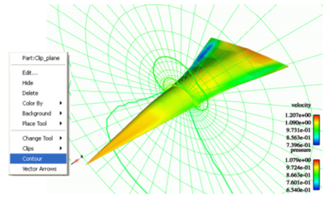
If the preference called Color by creation variable toggle is set the contour loops are colored by velocity. If this toggle is not set, the contours will appeared as white lines initially (and can be colored later if desired). We can change the line width of the contours to make them a little more visible.
Click the Part Line Width pulldown from the Quick Action Icon Bar and set the width to 3 pixels. Your Graphics Window should look something like:
Alternatively, you could have right-clicked on the clip plane part and chosen contour.
See Create Contours for more information on contours and how color palettes affect contours.
Clip parts in EnSight can be interactive: the tool that created the part can be grabbed with the mouse and moved. Or in cases like our X plane, a slider is provided. Once you release the mouse button, any parts that depend on the clip (i.e. that have the clip part as a parent), are automatically recalculated to reflect the new condition of the parent.
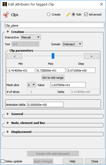
Double-click the Clip_plane part in the Parts list. (Or right-click and Edit.)
Double-clicking a created part opens the Feature Panel and places it into Edit mode. Any changes in the Feature Panel will affect only the parts marked with a pencil in the Parts list.
Click the Interactive pulldown and select Manual.
Manipulate the slider.
As the slider moves, the X plane is translated.
When the slider is released, the contour part recalculates to reflect the ending location of the clip plane. You can also type precise locations into the X Value field (and press Enter) if desired. You can also click the slider arrow buttons, which stride by the increment value.
Alternatively, you can left click the clip plane until you get a handle and then drag the clip plane using the left mouse button on the handle.
If the Feature Panel is no longer showing the Clip_plane part, change the value of the Sublevels field to 3 to redisplay the part’s Feature Panel, then click the Interactive pulldown again and select Off to disable interactive operation.
See Create Contours for more information on contours and how color palettes affect contours.
Important: Any kind of part (model or created) can be deleted, however, a deletion cannot be undone.
Select all created parts in the Parts list. Place the mouse pointer over part 3, click the left mouse button then Shift click on part 4 so it is selected as well.
Right-click and Delete (or move the mouse into the graphics window and press the delete key, or choose Main Menu → Edit → Part → Delete...) and confirm the deletion if prompted.
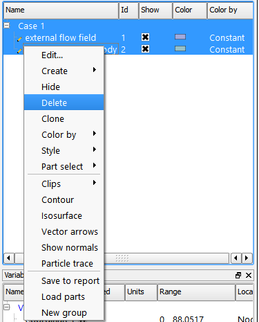
The parts are removed from the display and the Parts list.
Isosurface Part
Another type of created part is an isosurface. An isosurface is a surface of constant value (the isovalue ) in a 3D field. The region on one side of the isosurface has values greater than the isovalue and the region on the other side has values less than the isovalue. To create an isosurface:
Select the external flow field part in the Parts list.
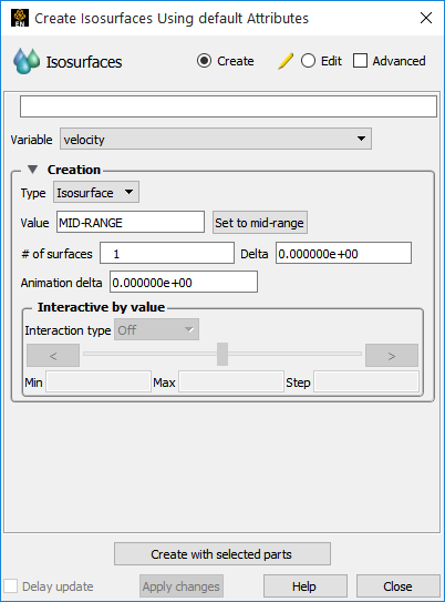
Click the Isosurface icon in the Feature Icon Bar to open the Feature Panel.

Select pressure in the variables pulldown.
Triple-click the Value field to select the MID-RANGE value. Type
0.9.Click Create with selected parts to build the isosurface part.
Color the new isosurface part by pressure by right-clicking on the part (in the graphics window or in the Parts list) to Color By → Select Variables and choosing pressure in the resulting pop-up dialog.
Isosurfaces can be interactive. Manipulating a slider changes the isovalue and the isosurface is recalculated and redisplayed.
Change the Interactive setting from Off to Manual.
Grab the slider and move it left and right.
The isosurface changes as the slider is moved. Or better, left-click on the isosurface to see a part handle. Left click and drag to change the isovalue.
Turn the Interactive mode Off, and delete the isosurface part.
See Create Isosurfaces for more information.
Particle Trace Part
EnSight provides particularly powerful tools for exploring flow with particle traces. Traces can be emitted from a point, a line, a plane, or even the nodes of an arbitrary part. A trace emitter can be made interactive: moving the emitter with the mouse will recalculate and re-display the traces. In this example, a simple point trace will be created. As before, the operation can be performed through the user interface or via right-click. We will use right-click.
Click the Reinitialize Transforms icon to reset the view back to the default.
Click the Cursor tool toggle.
The Cursor tool is used to specify the position of a 3D point and, in this case, will be used to set the location of the particle trace emitter. Unfortunately, the Cursor may not be visible and may be initialized inside the hypersonic body part. The part needs to be made temporarily invisible so the Cursor can be moved.
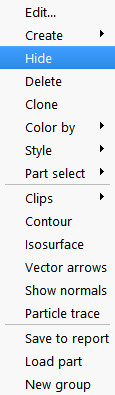
Right-click the hypersonic body part in the Parts list to Hide.
You should now see the Cursor tool (the red, green, blue cross) in the center of the screen.
Move the mouse pointer into the Graphics Window and directly on top of the center of Cursor tool.
Note: The mouse cursor will change to a + shape when over the tool.
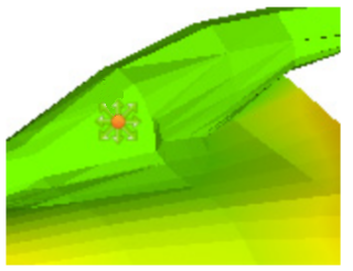
Click and hold the left mouse button and drag the Cursor to a location up and to the left (see image below).
Turn the visibility of the hypersonic body back on by again right-clicking on it (this time it can only be done in the Parts list) and select Show.
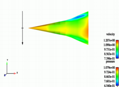
Your Graphics Window should look something like the following:
Select the external flow field part in the Parts list. This will be the part (“parent part”) we trace the particle through.
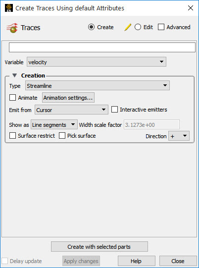
Click the Particle Traces icon in the Feature Icon Bar to open the Feature Panel.
Select velocity in the variable pulldown in the Feature Panel.
The Emit From setting in the Feature Panel is set to Cursor by default.
Click Create with selected part, to trace the particle.
Note: This could have also been done by right clicking on the cursor tool.
The trace should be visible extending from the Cursor tool to the right and down over the hypersonic body. See Use the Cursor (Point) Tool (Help → How to manual...) for more information on manipulating the Cursor tool.
EnSight can also trace from the Line tool to create a rake of particles. This can also be done via the right-click capability but we will do it here by following the user interface.
Right-click the particle trace part in the Parts list and delete it.
Click the Cursor toggle on the desktop to disable display of the Cursor tool and click on the Line toggle to turn the line tool visible.

This selection displays the Line tool which is also completely enclosed within the hypersonic body part.
Right-click the on the hypersonic body part and choose Hide to disable part display. The Line tool (oriented horizontally) should now be visible.
Move the mouse pointer into the Graphics Window and directly on top of the center of Line tool. (The mouse cursor will change to a + when over a tool hotpoint.)
Click and hold the left mouse button and drag the Line to a location up and to the left.
Click the Part Visibility Toggle to re-enable display of the hypersonic body part.
Select the external flow field part in the Parts list.
Click on the Particle Trace icon in the Feature bar to bring up the Particle trace Feature Panel.

Move the mouse pointer back into the Graphics Window and directly over the right end of the Line tool.
Click and drag the end of the Line tool down and to the left such that the Line is vertically stretched across the front of the hypersonic body (see image below).
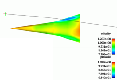
Your Graphics Window should look something like the following:
Select velocity from the variable pulldown.
Select Line to Emit From.
Change the # Points field to
12.Make sure that the external flow field is selected in the Parts list as the parent part.
Click Create with selected parts.
This operation created 12 evenly spaced traces along the Line tool.
Interactive particle traces are particularly useful for exploring fluid flow
In order to make the traces interactive you must click Interactive Emitters.
Move the mouse pointer into the Graphics Window and directly over the center of the Line tool.
Click and hold the left mouse button and drag the Line tool up and down. Release the mouse button.
The constituent traces are recalculated and re-displayed as the Line tool moves. It may help to rotate the model to a new orientation and then move the Line tool again.
Click Interactive Emitters again to disable interactive operation.
See How To Create Particle Traces (Help → How to manual...) for more information on particle tracing.
Particle traces can be animated to provide intuitive comprehension of flow characteristics. Traces are animated by displaying one or more tracers on all traces of the trace part. A tracer moves along the path of a trace with length proportional to the local velocity. EnSight provides complete control over all aspects of the tracers including length, speed, and release interval for multiple pulses.
Toggle Animate.
The tracers can be seen moving down the length of the traces. Numerous controls are provided for altering the appearance and behavior of the tracers.
It may be beneficial to turn off Highlighting - see step 2 under Feature Demonstration.
Click Animation settings... to open the Trace Animation Settings dialog.
Click Get Defaults to load suitable default values to the various trace parameter fields.
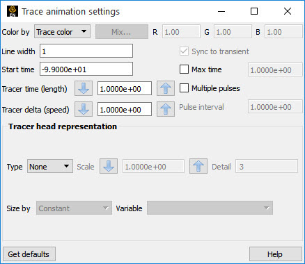
Click Multiple Pulses.
Note: There are now several tracers are moving down each trace. The Pulse Interval field controls the spacing between tracers.
Triple-click in the Pulse Interval field to select the value. Type
10and press Enter.You can lengthen or shorten the tracer via the Tracer Time field. Either enter a new value (like 1.0) or use the up/down arrows to modify the value.
The speed of the tracers is controlled by the Tracer Delta field. Enter a val (try 0.1 for example) or use the up/down arrows.
Click the X to Close the dialog.
Animating traces often look better with the trace part invisible.
Right-click the particle trace part and select Hide in the pulldown.
Click the Line Tool icon to disable the display of the Line tool.

Quit EnSight ( → → )
See Animate Particle Traces (Help → How to manual...) for more information on trace animation.