Optimizing for a Specified Frequency
-
Automatic mesh refinement is
off by default, but you can turn it on to automatically refine the mesh during
optimization.
- From the Simulation tab ribbon, select the Global dropdown menu. The Global fidelity options appear.
-
For Automatic mesh refinement, click
 and select Program
controlled.
and select Program
controlled.
-
Once you have a faceted geometry result you want to save, click
 in the Results Arc to
save it to the model. The new faceted geometry is now listed in the Model tree.
in the Results Arc to
save it to the model. The new faceted geometry is now listed in the Model tree.
-
Right-click the faceted body in the Model tree to perform any of the following
actions:
Option Description Create Validation Simulation Once the topo opt simulation is complete, and you have created a faceted body of the resulting optimized shape, select this option to create a new simulation that includes all of the physics conditions from the topology optimization simulation applied to the faceted body. This could be a single test or multiple test cases depending on the topo opt setup.
This option automatically creates a validation simulation of the faceted geometry created from the topology optimization simulation.
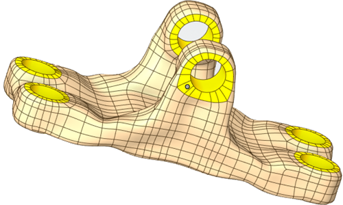
Smooth Facets Select this option to smooth your shape. A new faceted model appears in the Model tree. Convert to SubD hybrid Select this option to convert your faceted shape to a hybrid model and add it to the Model tree. The hybrid model contains both subdivision surfaces for regions of the model where you want to allow for flexible and freeform editing and traditional surfaces such as planes or cylinders for regions requiring precise topology.
Once you have created the hybrid model of the resulting optimized shape, you can right-click the hybrid model in the Model tree and select the Create Validation Simulation option to create a validation simulation that includes all of the physics conditions from the topology optimization simulation applied to the hybrid model.
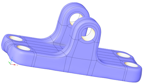
Select this option to smooth the facets, fit surfaces onto the facets, then create a solid body by stitching those patches together whenever possible. The patched body is then added to the Model tree.
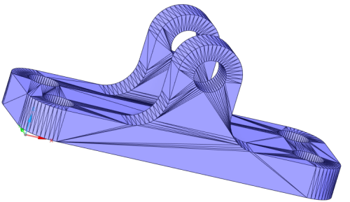
Select this option to convert your faceted shape to a solid model and add it to the Model tree, with the facets in flat areas merged together. As seen in this image, that means that curved areas will still have a faceted shape.
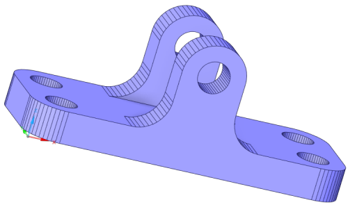 Select this option to convert your faceted shape to a solid model and add it to the Model tree, with the facets converted to faces on the solid.Note: The more facets there are on the shape, the longer the conversion will take.