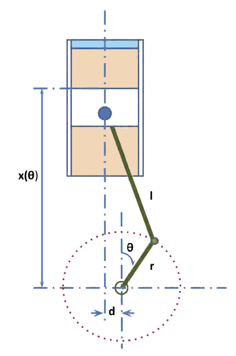
The schematic in Figure 8.7: Schematic of an engine cylinder with a positive piston offset shows the configuration of an engine cylinder with the centerline of the piston pin shifted to the left of the crank shaft by an amount of . A negative
value means the piston pin is located to the right of the crank shaft center. The crank shaft radius is
, the connecting rod length is
, and the bore diameter is
. The nominal values of the clearance volume of the cylinder and the compression ratio are
and
, respectively.
The location of the top piston surface above the crank shaft center x can be expressed as a function of crank angle :
(8–48) |
The crank angle (in radians) is a function of time and engine speed (in rpm) and is given as
, in which the angular velocity of the crank shaft is
.
A positive piston offset will lead to top-dead center (TDC) advance and its effects on piston movement are illustrated by Figure 8.8: Comparison of piston location ( ) versus crank angle (
in degree) between engines with positive piston offset and without piston offset (
and
=0.4) . A "negative" piston offset (that is, the piston pin is to the right of the crank shaft) will result in retarding TDC.
The actual TDC of an engine with a piston offset of can be found as
(8–49) |
And the bottom dead center (BDC) is located at
(8–50) |
The actual stroke can be computed as
(8–51) |
Subsequently, the piston velocity can be derived by taking the time-derivative of the piston location :
(8–52) |
The instantaneous cylinder volume can be found to be:
(8–53) |
and the rate of change of the cylinder volume is the time-derivative of the cylinder volume:
(8–54) |
The internal surface area of the cylinder (for wall heat transfer calculations) is
(8–55) |
or
(8–56) |
is the cylinder-head-to-bore area ratio, and
is the piston-head-to-bore area ratio. The default value of the area ratios is 1.
Figure 8.8: Comparison of piston location ( ) versus crank angle (
in degree) between engines with positive piston offset and without piston offset (
and
=0.4)


