


After establishing the Reactor Model connections and Pre-processing the chemistry set, you can begin entering the parameters that define the reactor conditions. For this thermal-cycle model, only a limited number of parameters are required. If a field or value is not required, it may be left blank to enable default behavior. The following steps assign the necessary user input.
Note: Labels for required parameters are always highlighted in bold font on the panels.
Double-click the Cluster Properties node on the Open Projects tree and go to the Properties for All Reactors tab.
Select the Solve Gas Energy Equation option in the Problem Type pull-down menu.
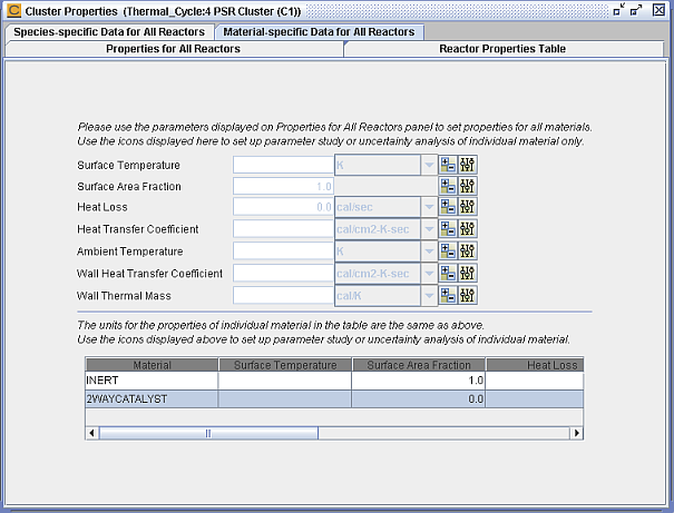
Select the Material-specific Data for All Reactors tab. As shown in Figure 2.37: Cluster Properties—Material-specific Data for All Reactors, enter the two surface area fractions for materials INERT and 2WAYCATALYST. For this initial problem we will only use an inert (non-reactive) surface material.
All of the reaction properties can also be conveniently entered through a spreadsheet-like table on the Reactor Properties Table tab.
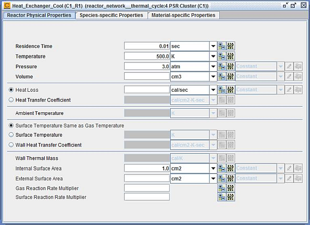
Double-click the Heat_Exchanger_Cool (C1_R1) node on the Open Projects tree. In the Reactor Physical Properties tab set the reactor residence time, temperature, pressure, and internal surface area, as shown in Figure 2.38: Heat_Exchanger_Cool (C1_R1)—Reactor Physical Properties.
Select the Species-specific Properties tab. Enter the initial guesses for gas fractions to be the composition of air in the Initial Gas Fraction sub-tab as shown in Figure 2.39: Heat_Exchanger_Cool (C1_R1)—Species-specific Properties.
Note: You can also enter whole numbers: 21 for O2 and 79 for N2. You can then click the Normalize button to see that Ansys Chemkin will always normalize species fractions to summarize to unity. If you do not manually normalize the species fractions, Chemkin will automatically do this during the run.
Note: An alternative to entering species fractions on the Species-specific Properties tab is to use the Import button to import data from a file, either tab-delimited or space-delimited. The first line must provide the Unit Selection, exactly as specified on the Species-specific Properties tab. If the species has no unit, provide
noneas the unit. Each line in the imported file should have the format:Comma-delimited:
species_name, mole_fraction_valueExample: mole fraction (or mole) O2, 0.21 N2, 0.79
Space-delimited:
species_name mole_fraction_valueExample: mole fraction (or mole) O2 0.21 N2 0.79
Double-click the Burner (C1_R2) node on the Open Projects tree. On the Reactor Physical Properties tab, enter the residence time, temperature, pressure, and internal surface area as shown in Figure 2.40: Burner (C1_R2)—Reactor Physical Properties. Note that although Volume is indicated as required by highlighting in bold font, you do not have to provide a value for it, because we are providing flow rate and residence time. For more information, see the bubble help by holding the mouse over Volume.
Double-click the Water_Heater (C1_R3) node on the Open Projects tree. In the Reactor Physical Properties tab, specify the parameters shown in Figure 2.41: Water_Heater (C1_R3)—Reactor Physical Properties.
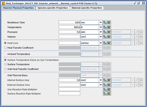
Double-click the Heat_Exchanger_Hot (C1_R4) node on the Open Projects tree. On the Reactor Physical Properties tab, enter the parameter values shown in Figure 2.42: Heat_Exchanger_Hot (C1_R4)—Reactor Physical Properties.
Double-click the Secondary_Air inlet node on the Open Projects tree. Dismiss the message that reminds you to provide inlet species composition data. In the Stream Properties Data tab, enter the mass flow rate and inlet temperature, as shown in Figure 2.43: Secondary_Air—Stream Properties Data.
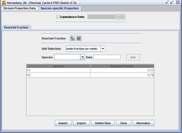
Select the Species-specific Properties tab. Specify the inlet gas composition as air consisting of 79% nitrogen and 21% oxygen, as shown in Figure 2.44: Secondary_Air—Species-specific Properties.
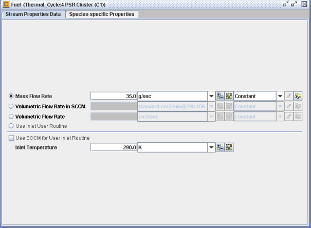
Double-click the Fuel inlet node on the Open Projects tree. Dismiss the message that reminds you to provide inlet species composition data. In the Stream Properties Data tab, enter the mass flow rate and inlet temperature as shown in Figure 2.45: Fuel—Stream Properties Data.
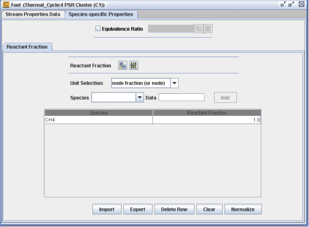
Select the Species-specific Properties tab and enter the inlet composition as pure methane (CH4) in the Reactant Fraction sub-tab, as shown in Figure 2.46: Fuel—Species-specific Properties.
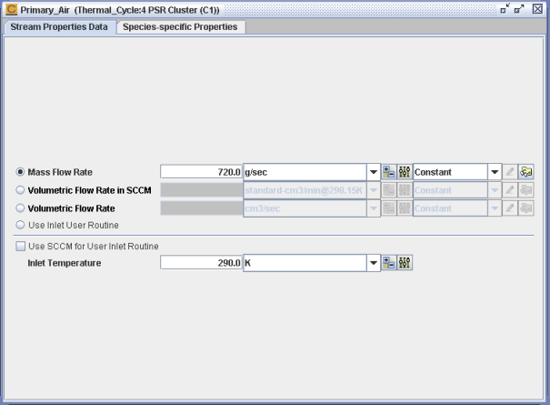
Double-click the Primary_Air inlet node on the Open Projects tree. Dismiss the reminder message. Enter the stream properties in the Stream Properties Data tab as shown in Figure 2.47: Primary_Air—Stream Properties Data.
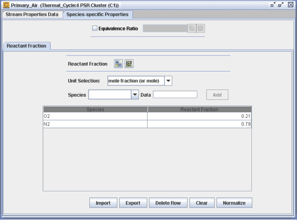
Select the Species-specific Properties tab and set the Reactant Fraction values to air as shown in Figure 2.48: Primary_Air—Species-specific Properties.
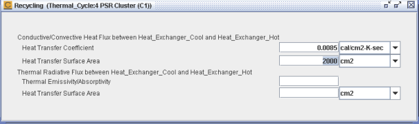
Double-click the Recycling node on the Open Projects tree. This panel is used to enter parameters governing heat and mass transfer between reactors within a cluster. Enter the heat-transfer parameters as shown in Figure 2.49: Recycling.
Use Ctrl-S to save all the data you have entered. The input parameters entered at this point are sufficient for the thermal-cycle project. Default values in other panels are assumed.
Note: To close all open panels in a project, you can click the " twistie" to the left of the cluster-level (for example, Cluster1) or project-level nodes, as shown in Figure 2.2: Open Projects Palette. When the twistie is in the horizontal position, all panels associated with nodes within that branch of the tree will be closed.
Now you are ready to run this model. At the project-level of the tree, double-click on the Run Calculations node. Use the Run Calculation panel’s Begin button to launch the simulation. The Monitor Project Run panel displays. This model should take one or two minutes to run on a moderately powered PC. When the run completes successfully, the Diagram and Monitor Project Run panels close and the Analyze Results panel opens.
Save the project again (Ctrl-S). This will save the input file name, output file names, and any supplemental input to the project file.
-Reactor_Phys_Props.png)
-Reactor_Phys_Props.png)
-Reactor_Phys_Props.png)

Note: If you have errors running your simulation, detailed error messages are provided in the output files. Click View Output File to view any output diagnostics.