


The Injection Details tab defines geometric parameters and fluid conditions at the injection positions.
You can optionally use CEL expressions to specify details at the injection positions. For example, you can specify
injection hole diameters using data from the same profile function that defines the injection positions (see User Functions for Injection Regions).
To do this, you could set Diameter to Injections.Diameter(x,y,z)
where Injections is the user function name in this example.
The available options are:
Circular HoleWith the
Circular Holeoption, each injection position has a circular hole with the specified Diameter.Cylindrical HoleThe
Cylindrical Holeoption is available only when, on the Basic Settings tab, Injection Location Type > Option is set toSelected 2D Regions.With the
Cylindrical Holeoption, each injection position has a hole that is not necessarily circular; the shape is formed by the intersection of the selected 2D regions and the cylinder. The cylinder has the specified Diameter. The orientation of the cylinder is controlled by the Hole Direction settings (see Hole Direction).Axisymmetric SlotThe
Axisymmetric Slotoption is available only when, on the Basic Settings tab, Injection Location Type > Option is set toSelected 2D Regions.With the
Axisymmetric Slotoption, each injection position has a rectangular hole that is aligned circumferentially to an axis of rotation. The size of the hole is defined by a Slot Width and a Slot Pitch (which is the angular extent of the slot in the circumferential direction).An additional Axis Definition might be required if the parent domain is not already specified as rotating.
User Defined SlotThe
User Defined Slotoption is available only if the Injection Positions specifications (Basic Settings tab) contains line connectivity data.The slot has the specified Slot Width.
For details, see User Defined Slots and Cylindrical Slots.
Cylindrical SlotThe
Cylindrical Slotoption is available only if the Injection Positions specifications (Basic Settings tab) contains line connectivity data.The slot has the specified Slot Width.
The
Cylindrical Slotoption is similar to theUser Defined Slotoption but is more suitable for use in geometries that have rotational periodicity or are generally axisymmetric.For details, see User Defined Slots and Cylindrical Slots.
The Hole Direction settings define the direction of a cylinder that intersects with the selected 2D regions at an injection position to define the corresponding hole geometry.
These settings are available only when Injection Location Type is set to Selected 2D Regions and Injection Model
> Option is set to Cylindrical Hole (for the Circular Hole option, the hole is directed along
the local normal of the selected 2D regions).
There are four options for the hole direction:
Normal to Boundary ConditionThe hole is directed along the local surface normal at the injection position.
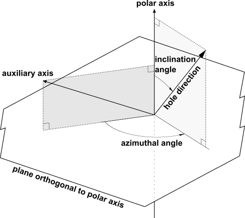
Local Spherical AnglesYou must specify an Inclination Angle and an Azimuthal Angle, which are used within a local coordinate frame that is defined by Polar Axis and Auxiliary Axis direction vectors (which are not parallel). The hole direction is determined by rotating away from the local Polar Axis, towards the Auxiliary Axis, by the Inclination Angle, then further rotating around the local Polar Axis, in a direction consistent with the right-hand rule, by the Azimuthal Angle.
Cylindrical ComponentsThe hole is directed along the specified direction vector.
Cartesian ComponentsThe hole is directed along the specified direction vector.
The User Defined Slot and Cylindrical Slot options are similar in that they allow you to define
a slot that forms an arbitrary curvilinear shape, made up of connected line segments (that is, a polyline).
The Injection Positions (Basic Settings tab) define the location of the line segments, and the orientation is derived
from the position of the neighboring points. The slot will terminate exactly at the defined
start and end positions of the polyline, and thus the slot length is implied directly by these
positions. The transverse size of both of these slot options is defined by a Slot Width, which
is symmetrical either side of the centerline defined by the Injection Positions.
The User Defined Slot is defined and intersected with the selected 2D regions in Cartesian
space. As such it is very flexible in its application.
The Cylindrical Slot is intersected with the selected 2D regions within a cylindrical coordinate
frame, and as such an additional Axis Definition might also be required if the parent domain is
not already specified as rotating. The selected 2D regions are assumed to be surfaces of
revolution; this is exploited within the intersection process.
Note: For both the Cylindrical Slot and User Defined Slot options,
the Injection Positions specification
must contain line connectivity data. That is, the corresponding Injection Positions specification
(see Injection Positions) must refer to either a user line or a profile user function containing a "[Lines]"
definition. The connectivity data does not have to be sequential and can form multiple
disconnected line segments. However, in order to form a single line segment, the Injection
Positions specification must contain at least two points.
Note: Because the Cylindrical Slot option uses a cylindrical coordinate frame to
calculate the intersection with the underlying surface, issues can arise if a slot segment,
which is based on a line segment between two specified points in the slot, crosses the discontinuity
that exists from  to
to  in the theta coordinate. This can lead to a distorted or unrealistic
overlap calculation, in which case the solver output includes a warning message. As a workaround,
you might consider taking any of the following actions:
in the theta coordinate. This can lead to a distorted or unrealistic
overlap calculation, in which case the solver output includes a warning message. As a workaround,
you might consider taking any of the following actions:
Re-orient the mesh about the cylindrical axis so that the slot avoids the discontinuity.
Switch to the
User Defined Slotoption to avoid using a cylindrical frame for intersection, thereby removing the discontinuity.Use the CCL printed in the warning message to produce some additional diagnostic CSV files that can be used to assess whether or not the calculated overlap is acceptable.
The only available option is Injection Mass Flow Rate.
Specify a positive value or expression for Mass Flow Rate; negative values are clipped to zero. If you need to change a source to a sink or vice versa, change the Region Type setting on the Basic Settings tab.
Indicate the applicability of the specified mass flow rate by selecting an option for Mass Flow Rate Area:
Total for All SectorsThe specified mass flow rate is the total mass flow rate for the complete 360° geometry, including all rotationally periodic sectors.
As SpecifiedThe specified mass flow rate is the mass flow rate for the specified region, whether or not the latter includes all sectors and irrespective of the number of injection positions.
Per Injection PositionThe specified mass flow rate is the mass flow rate for each individual injection position.
If profile data is used to specify the mass flow rate then using the
Per Injection Positionoption ensures that the correct data value is applied to each injection position.
This setting defines the direction of the flow from the hole.
The options are:
Injection Model(default)The fluid is directed along the specified Hole Direction.
Normal to Boundary ConditionThe fluid is directed along the local surface normal at the injection position.
Cartesian ComponentsThe fluid is directed along the specified direction vector.
Cylindrical ComponentsThe fluid is directed along the specified direction vector.
Select an appropriate turbulence option for the fluid entering the domain at the injection positions.
Turbulence > Option can be set to any one of the following values
Low (Intensity = 1%)Medium (Intensity = 5%)High (Intensity = 10%)Intensity and Eddy Viscosity Ratiok and Eddy Viscosity Ratio
Specify a static or total temperature for the fluid entering the domain at the injection positions.
If there are multiple frames of reference and the parent domain is rotating, indicate the frame of reference for a specified total temperature.