


The heat flux across the wall boundary is zero.
When radiation is included, the total heat flux is zero:
 | (2–7) |
For details, see CFX-Solver Output File (Radiation Runs) in the CFX-Solver Manager User's Guide.
For details on the related results file variable, see Wall Temperature (Tw ).
The wall boundary is fixed at a specified temperature  . The heat flux into the domain is calculated for laminar flows
from the temperature gradient at the wall, and for turbulent flows by:
. The heat flux into the domain is calculated for laminar flows
from the temperature gradient at the wall, and for turbulent flows by:
 | (2–8) |
where  is
the near-wall temperature and
is
the near-wall temperature and  involves the use of
turbulent wall functions. For details, see Heat Flux in the Near-Wall Region in the CFX-Solver Theory Guide.
involves the use of
turbulent wall functions. For details, see Heat Flux in the Near-Wall Region in the CFX-Solver Theory Guide.
For details on the related results file variable, see Wall Temperature (Tw ).
A heat flux is specified across the wall boundary. A positive value indicates
heat flux into the domain. For multiphase cases, when the bulk heat flux into
both phases is set, this option is labeled Wall Heat Flux instead of Heat Flux.
When set on a per fluid basis, this option is labeled Heat Flux.
For details on the related results file variables, see Wall Heat Flux and Heat Flux (qw ).
In this case, the heat flux at a wall boundary is implicitly specified using an external heat transfer coefficient, h c, and an outside or external boundary temperature, T o. This boundary condition can be used to model thermal resistance outside the computational domain, as in the diagram below:
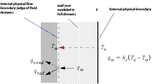
The heat flux at the Heat Transfer Coefficient wall is calculated using:
 | (2–9) |
where T
o is the specified outside
or external boundary temperature.  is the temperature at the wall (edge of the domain), which for
turbulent flows is calculated from a surface energy balance and for laminar
flows is the boundary temperature field calculated by the solver. The heat flux
q
w is the total heat flux from
conduction and radiation when radiation is modeled. For details, see CFX-Solver Output File (Radiation Runs) in the CFX-Solver Manager User's Guide.
is the temperature at the wall (edge of the domain), which for
turbulent flows is calculated from a surface energy balance and for laminar
flows is the boundary temperature field calculated by the solver. The heat flux
q
w is the total heat flux from
conduction and radiation when radiation is modeled. For details, see CFX-Solver Output File (Radiation Runs) in the CFX-Solver Manager User's Guide.
For details on the related results file variables, see Wall Heat Transfer Coefficient (hc ) and Wall Adjacent Temperature (Tnw ) and Wall External Heat Transfer Coefficient and Wall External Temperature.
Temperature data is set according to System Coupling. For details, see Coupling CFX to an External Solver: System Coupling Simulations in the CFX-Solver Modeling Guide.
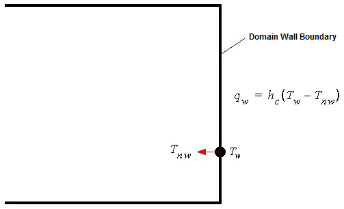
The results file contains several wall-only variables when the Thermal or Total Energy heat transfer models are active. Figure 2.5: Variables at a Wall Boundary depicts the variables that can be written at a wall boundary condition.
The following sections provide details about these wall-only results file variables:
This is the hybrid temperature field at a wall boundary condition. For Fixed
Temperature walls, the wall temperature is the specified value
 . For all other heat
transfer boundary conditions, the wall temperature is calculated from turbulent
wall functions when running a turbulent flow model. For laminar flow modeling
the wall temperature is just the local fluid temperature at the vertex adjacent
to the wall.
. For all other heat
transfer boundary conditions, the wall temperature is calculated from turbulent
wall functions when running a turbulent flow model. For laminar flow modeling
the wall temperature is just the local fluid temperature at the vertex adjacent
to the wall.
When running the inhomogeneous heat transfer model, this variable is written per fluid. Similarly, for a porous solid, this variable is written for the solid phase as well.
Wall Heat Flux is the total heat flux into the domain,
including convective and radiative contributions. There are also variables
called Wall Convective Heat Flux and Wall
Radiative Heat Flux for the separate convective and radiative
contributions.
When running the inhomogeneous heat transfer model, this variable is written per fluid. Similarly, for a porous solid, this variable is written for the solid phase as well.
Heat Flux is also the total heat flux into the domain,
including convective and radiative contributions. This variable is different
from the Wall Heat Flux in several ways:
There are no equivalent separate variables for the convective and radiative components.
It can be plotted local to a specific boundary condition.
Wall Heat Fluxcontains contributions from adjacent boundary conditions. For example, edge values ofHeat Fluxon a heat-transfer coefficient boundary are not affected by being adjacent to an adiabatic wall.It is computed on boundary vertices by the post processor directly from the energy flows written to the results file by the CFX-Solver, and the geometric area of the control volume face at the boundary vertex. This is sometimes advantageous over the
Wall Heat Fluxvariable in that it eliminates the arithmetic averaging procedure used by the CFX-Solver to computeWall Heat Fluxat each boundary vertex from the faces adjacent to each vertex. For porous domains, the use of the geometric area introduces another difference to theWall Heat Fluxvariable since the CFX-Solver uses the phasic area (geometric area * fluid/solid volume porosity) instead of the geometric area at the boundary face.Heat Fluxshould be used in preference toWall Heat Fluxwhen this is possible.
In the CFX-Solver the heat flux variables available for use in expressions are
just Wall Heat Flux and Wall Convective Heat
Flux. These variables are based on energy flows and so are
equivalent to the variable Heat Flux and its convective
component in the post-processor.
These two variables are calculated as part of the convective heat transfer at a wall.
Laminar flow model:
Wall Heat Transfer Coefficient,
 ,
is calculated by rearranging the expression for the convective heat flux
in Equation 2–8 and setting
the wall temperature as described above.
,
is calculated by rearranging the expression for the convective heat flux
in Equation 2–8 and setting
the wall temperature as described above.Wall Adjacent Temperature,
 , is the average temperature in the
element adjacent to the wall.
, is the average temperature in the
element adjacent to the wall.
Turbulent flow model:
Wall Heat Transfer Coefficient is given by the thermal wall functions. The theory of thermal wall functions can be found at Heat Flux in the Near-Wall Region in the CFX-Solver Theory Guide.
For turbulent flow without viscous work active, the Wall Adjacent Temperature is the conservative (solved for) temperature in the control volume adjacent to the wall. On the other hand, if viscous work is active, Equation 2–267 in the CFX-Solver Theory Guide, can be rearranged as:

(2–10)
Therefore, with viscous work active, the Wall Adjacent Temperature becomes:

(2–11)
For details of the treatment of heat transfer at a wall for turbulent flows, refer to the discussion of Heat Flux in the Near-Wall Region in the CFX-Solver Theory Guide.
These variables are written for boundaries that have a specified external heat transfer coefficient and a specified external boundary temperature.
Additional information for multiphase cases is available. For details, see Wall Boundaries in Multiphase.