


The General Connection interface model is a powerful way to
connect regions together. A general connection can be used to:
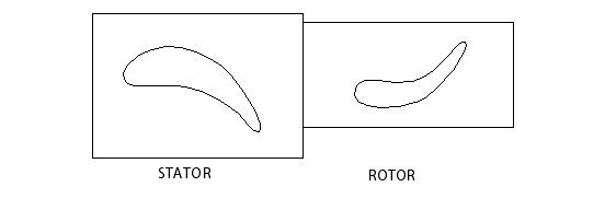
Apply a frame change at the interface between a rotor and stator
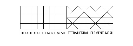
Connect non-matching grids
Apply fully transient sliding interfaces between domains
Pitch change can also be applied. For example, a domain interface can connect a stator domain with a rotor domain where the number of stator blades is not equal to the number of rotor blades, even if the mesh contains only one blade from each side.
Examples of the general connection type are shown below:
The General Connection option is necessary when the frame of
reference or pitch changes across the interface. For example, the general connection
option must be used in the following cases:
One side is in a stationary frame of reference and the other side is in a rotating frame of reference
Both sides are in a rotating frame of reference but each with a different rate of rotation
Both sides are in the same frame of reference but have unequal pitches. In this situation, the flows through the interface must account for pitch change.
When a general connection is selected, the following details need to be specified:
There are three types of frame change/mixing models available in Ansys CFX:
Frozen RotorStage (Mixing-Plane)Transient Rotor-Stator
Each side of the interface must be a surface of revolution and both sides must sweep out the same surface of revolution.
The frame of reference and/or pitch is changed but the relative orientation of the components across the interface is fixed. The two frames of reference connect in such a way that they each have a fixed relative position throughout the calculation. If the frame changes the appropriate equation transformations are made. If the pitch changes, the fluxes are scaled by the pitch change.
This model produces a steady-state solution to the multiple frame of
reference problem, with some account of the interaction between the two
frames. The quasi-steady approximation involved becomes small when the
through flow speed is large relative to the machine speed at the interface.
Frozen Rotor analysis is most useful when the
circumferential variation of the flow is large relative to the component
pitch. This model requires the least amount of computational effort of the
three frame change/mixing models.
The disadvantages of this model are that the transient effects at the frame change interface are not modeled. Modeling errors are incurred when the quasi-steady assumption does not apply. Also, the losses incurred in the real (transient) situation as the flow is mixed between stationary and rotating components is not modeled.
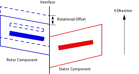
The Rotational Offset settings control the angle by which the side 1 or side 2 domains are rotated before the interface calculation is performed. The domain axis of rotation is used to perform the rotation. The rotational offset that is applied to the domains on side 1 or 2 depends on whether domains are rotating on side 1, 2, both, or none. The ways in which rotational offsets are stored in results file and are interpreted by CFD-Post are:
If the side 1 domains are rotating and the side 2 domains are stationary then a rotational offset will be written for the side 1 domains, and interpreted by CFD-Post.
If the sides 1 and 2 domains are rotating then a rotational offset will be written for the side 1 domains, and interpreted by CFD-Post.
If the side 1 domains are stationary and the side 2 domains are rotating then a rotational offset will be written for the side 2 domains, and interpreted as a counter-rotation by CFD-Post.
If the sides 1 and 2 domains are stationary then a rotational offset will be written for the side 1 domains, but not interpreted by CFD-Post; the rotational offset will not be applied.
You can use a rotational offset if you want to change the relative position of the components on each side of the interface without altering the position of the meshes. The positive direction for an offset is determined by the right-hand rule. Figure 5.4: Rotational Offset shows how a rotational offset will alter the relative position of a rotor and stator component.
Note: As an alternative to the Rotational Offset parameter, you can also apply a domain rotation in CFX-Pre and create a new CFX-Solver input file.
By default, the domain positions are stored in their original
(non-offset) location. To have the domains appear in their offset
positions in CFD-Post, include the expert parameter rotational
offset for post=t in the problem definition and,
in CFD-Post, open Edit >
Options, then set the
CFD-Post > General option
Angular Shift for
Rotating Locations to Always
rotate. Click to save the
change.
The Stage model (also known as the Mixing-Plane model) is an alternative
to the Frozen Rotor model for modeling frame and/or pitch change.
Instead of assuming a fixed relative position of the components, the Stage
model performs a circumferential averaging of the fluxes through bands on
the interface. Steady-state solutions are then obtained in each reference
frame. This model enables steady-state predictions to be obtained for
multi-stage machines. The stage averaging at the frame change interface
incurs a one-time mixing loss. This loss is equivalent to assuming that the
physical mixing supplied by the relative motion between components is
sufficiently large to cause any upstream velocity profile to mix out prior
to entering the downstream machine component. Stage
analysis is most appropriate when the circumferential variation of the flow
is of the order of the component pitch.
Stage averaging between blade passages accounts for
time average interaction effects, but neglects transient interaction
effects. Stage analysis is not appropriate when the
circumferential variation of the flow is significant relative to the
component pitch (for example, a pump and volute combination at off-design
conditions).
The Stage model usually requires more computational effort than the Frozen Rotor model to converge, but not as much as the transient rotor-stator model. You should obtain an approximate solution using a Frozen Rotor interface and then restart with a Stage interface to obtain the best results.
The pressure profile at a Stage (Mixing-Plane) interface is determined by extrapolation from the pressure profile just inside the interface location (just upstream or just downstream of the Stage interface, for the upstream and downstream sides respectively). Sometimes, this procedure is unstable and a small amount of stiffness must be added to the pressure profile rather than just letting it float. By default, the pressure profile is decayed by 5% towards a constant value. The amount of decay can be controlled by this setting. Using a 5% pressure profile decay is recommended.
At a Stage (Mixing-Plane) interface, the average static pressure within each band on both the upstream and downstream side of the interface is set to the average band pressure. Here are possible treatments for velocity on the downstream side:
It may be calculated as the average band velocity. (
Stage Average Velocity)It may be calculated from the average band total pressure and direction in the relative frame (
Constant Total
                                        Pressure
). Note that, in this case, the frame type will be rotating.
The constant total pressure options permit the downstream velocity
profile to naturally adjust to downstream influences. For
tightly-coupled components, the Constant Total
Pressure option provides a better approximation than the
Stage Average Velocity option. To obtain
results comparable to CFX-TASCflow, use Constant Total
Pressure, Frame
Type=Rotating.
This model should be used any time it is important to account for
transient interaction effects at a sliding (frame change) interface. It
predicts the true transient interaction of the flow between a stator and
rotor passage. In this approach the transient relative motion between the
components on each side of the GGI connection is simulated. It ultimately
accounts for all interaction effects between components that are in relative
motion to each other. The interface position is updated each timestep, as
the relative position of the grids on each side of the interface changes. It
is possible to use a transient sliding interface anywhere a
Stage or Frozen Rotor sliding
interface could be used.
The principle disadvantage of this method is that the computer resources required may be large, in terms of simulation time, disk space and quantitative postprocessing of the data. The resource requirement problem is exacerbated if unequal pitch between components occurs. In these situations, spatial periodicity cannot formally be used to limit the analysis to a single blade passage per component. Often the problem of unequal pitch is addressed by modifying the geometry to the nearest integer pitch ratio, which may affect the validity of the analysis. In practice, components of unequal pitch can be treated by solving N passages on one side and M passages on the other side, with N and M determined such that the net pitch change across the interface is close to unity. As with a Frozen Rotor interface, pitch change is automatically accounted for by scaling of flows by the pitch ratio.
It is possible to start a Transient Rotor-Stator
computation from a simple initial guess, or from an existing prediction. If
you are interested in the start-up transient of the machine, then start from
the appropriate physical initial conditions. If you are interested in
simulating a periodic-in-time quasi-steady-state, then it may be helpful to
first obtain a steady-state solution using Frozen Rotor
interfaces between components. This solution will contain most of the
overall flow features, and should converge to the desired transient
simulation in the fewest transient cycles.
Translational relative motion is not supported at a transient sliding interface (only rotational motion is supported).
To connect dissimilar meshes, an intersection algorithm is used to find the overlapping parts of each mesh face at the interface; for details, see GGI and MFR Theory in the CFX-Solver Theory Guide. The CFX-Solver must decide the most appropriate way to perform this intersection. The choices are:
Intersect in physical space. The connection will be made as is with no correction for pitch change or rotational offset. This method is used when the pitch change model is set to
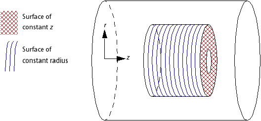
None.Intersection in the radial direction. This method is used when the pitch change model is not
Noneand the radial variation at the interface is larger than the axial (z-) variation. For example, this method is used for the surface of constant z in Figure 5.5: Radial vs. Z Direction.Intersect in the axial direction. This method is used when the pitch change model is not
Noneand the axial variation at the interface is larger than the radial variation. For example, this method is used for the surface of constant radius in Figure 5.5: Radial vs. Z Direction.
If the pitch change model is not None, then the
intersection algorithm will fail if the interface has any of the
following:
surfaces of zero radius
surfaces of constant radius with surfaces of constant z
For example, an interface cannot contain both highlighted regions in Figure 5.5: Radial vs. Z Direction. Instead, two separate interfaces should be used.
In addition, for best accuracy, the interface should not be highly curved. For example, if a small change in radius produces a large change in z and a small change in z produces a large change in radius in the same interface, then separate interfaces should be used instead.
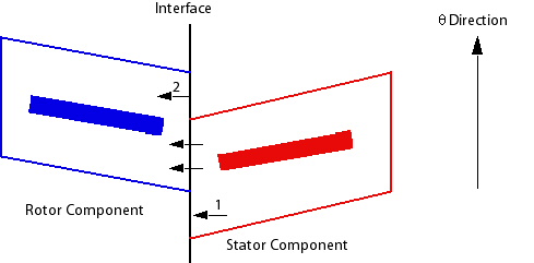
When there is pitch change, a transformation is also performed between components to account for the fact that they may not be rotationally aligned. This does not affect the relative position of the components. In Figure 5.6: Misaligned Components the components are not aligned; flow passes through the overlapping area as expected, but the flow that reaches the interface at 1 is transformed such that it emerges at 2 having crossed the interface.
Using None as the pitch change option will cause the
connection to be made "as is." If you have non-aligned
components, as shown in Figure 5.6: Misaligned Components, flow
will only pass through the overlapping region. Therefore, this option should
only be used when the overall extent and shape of each side of the interface
perfectly match and the surfaces are aligned with each other. It may
therefore be suitable when full 360 degree or exactly equal pitch components
are being analyzed. A pitch change option of None
cannot be used for a stage interface.
The Automatic pitch change option is the standard
option for accounting for pitch change between components. The pitch ratio
is taken to be the ratio of the areas of the two components. The two sides
must each have the same radial or axial extent and can therefore only differ
in extent in the direction of rotation of the frame of reference. This means
that the surfaces on each side of a frame change interface must sweep on the
same surface of revolution.
For the Frozen Rotor model, the flow variable profiles in the pitch-wise direction are stretched or compressed to the extent that there is pitch change across the interface. All flows (mass, momentum, energy, and so on) are scaled accordingly, based on the pitch change.
For the Stage (Mixing-Plane) model, the pitch change adjustment is made by applying average values calculated from the upstream side of the interface to the downstream side. The averaging is performed in a conservative manner. Meridional variation of the flow is maintained across the interface. Circumferential variation of all flow variables except pressure are removed across the interface. The average pressure is maintained at each meridional location across the interface, with independent local variation in pressure permitted.
The computational accuracy degrades rapidly with increasing pitch change. It is recommended that sufficient blade components be analyzed on each side of the interface to minimize pitch change. Any pitch change will result in a non-physical transient interaction: the entire 360 degree components must be solved for truly "accurate" transient interactions if the pitch ratio is non-integer. Small pitch changes will introduce relatively smaller errors, large pitch changes will introduce larger errors.
There are a number of scenarios where the algorithm used by the
Automatic pitch change option is not valid, such
as:
When the vertices on the intersection of the hub and interface are not all at the same radial and axial position
When one or both sides of the interface has a 360° or greater pitch angle
When one or both sides of the interface has a zero radius
When one or both sides of the interface has mesh faces normal and parallel to the rotation axis
When one or both sides of the interface has mesh faces at the hub (that is, low radial or axial position) that are thin in the radial or axial direction
When using the Automatic pitch change option, you
should examine the CFX-Solver Output file under the Mesh
Information heading to confirm that the calculated pitch
angles are sensible.
Using the Automatic pitch change option for
determining the pitch change may result in failure of the solver or a
solution that is completely wrong. An example of the flow solution being
wrong is flow exiting a non-overlapping region of the interface or flow not
exiting an overlapping area of the interface. In general if the flow
solution through the interface does not make sense, or if the calculated
pitch angles are not sensible in the CFX-Solver Output file, then you should use the
Value or Specified Pitch
Angles option.
This option enables you to explicitly provide the pitch ratio. This is the ratio of the pitch angle from the side with the larger pitch angle to the side with the smaller pitch angle across the domain interface. You can use this option when the precise pitch ratio is critical to the analysis; for example, in a closed system containing multiple pitched components.