


A user surface can be defined in a number of different ways:
From a file containing data points.
From the intersection of a boundary and an existing locator.
From a contour fringe number.
By transforming an existing surface.
Offset from an existing surface. The offset can be uniform or described by a variable.
Note: User Surface locators interpolate values using a method that is slightly less accurate than that used for slice planes and isosurfaces. For details, see Note.
The following characteristics of user surfaces will be discussed:
Note: There are several ways to insert a user surface:
From the menu bar, select Insert > Location > User Surface.
From the toolbar, select Location > User Surface.
Depending on the context, you may be able to perform an insert from the shortcut menu in the tree view.
The Method setting has the following options:
| Option | Description |
|---|---|
|
|
Same as for the polyline object. For details, see Polyline: Geometry: Method. The data file format is described in USER SURFACE Data Format. |
|
|
Same as for the polyline object. For details, see Polyline: Geometry: Method. |
|
|
Same as for the polyline object. For details, see Polyline: Geometry: Method. |
|
|
Create a user surface by transforming a preexisting surface. You may specify a rotation, translation, and uniform scale for the user surface. |
|
|
Create a user surface by offsetting it from a preexisting surface. You may specify different methods of offset for the user surface. |
|
|
Similar to the |
|
From STL File |
Similar to the You can also load STL files from the File menu in CFD-Post. For details, see Importing .stl Files. |
Note: When multiple cases are loaded, user surfaces defined
using either the Transformed Surface or Offset From Surface methods exhibit different behavior
depending on where the preexisting surface is:
The preexisting surface exists within domains from only one case.
Examples: a slice plane that intersects, or otherwise has been restricted to, the domains of only one case; a boundary that exists (by name) in only one case.
Result: The user surface exists in each loaded case, and has the same geometry for all cases.
The preexisting surface exists within domains of multiple loaded cases.
Examples: a slice plane that intersects the domains of multiple cases; a boundary that exists (by name) in multiple cases, and is selected in the list of preexisting surfaces specified by Surface Name.
Result: The user surface corresponds to the preexisting surface. That is, for every part of the preexisting surface that exists in each case, there is a corresponding part of the user surface that exists in the same case.
File is the same for the polyline object. For details, see Polyline: Geometry: File.
Tip: This method enables you to read surfaces from another case.
First export a surface (such as a plane or a boundary) from another
case and make sure to select Export Geometry Information and Export Line and Face Data. Then use the From File method in the other case to import the surface
along with any local data. You can also create a file containing your
own data, such as experimental data, by using the same format. For
a description of the surface file format, see USER SURFACE Data Format.
These settings are the same as for a polyline, except that instead of outlining the intersection, a line of intersection is formed between the boundaries and the location. Each mesh element that the line passes through forms part of the User Surface. For details, see Domains.
These settings are the same as for a polyline, except that instead
of outlining the contour, the User Surface fills in all of the area
above the contour level entered and below the contour level above.
Also, when applicable, Contour Level 1 creates a surface below the first contour line. For
details, see Contour Name.
Surface Name is available only if either
the Transformed Surface or Offset From
Surface options are selected. The Surface Name setting selects a surface on which to plot the User Surface.
The Rotation check box is available only
if the Transformed Surface option is selected.
Select the Rotation check box to specify a rotation
for the User Surface. For details, see Apply Rotation Check Box.
The Translation check box is available
only if the Transformed Surface option is selected.
Select the Translation check box to specify a
translation for the User Surface. For details, see Apply Translation Check Box.
The Scale check box is available only if
the Transformed Surface option is selected. Select
the Scale check box to specify a scale for the
User Surface. Use the Scale field to specify
a uniform scale factor.
Type is available only if the Offset From Surface option is selected. The Type setting has the following options:
| Option | Description |
|---|---|
|
| Enables you to offset the User Surface normal to selected surface. |
|
| Enables you to offset the User Surface from the selected surface by moving the User Surface. |
Mode is available only if the Offset From Surface option is selected. The Mode setting has the following options:
| Option | Description |
|---|---|
|
| Enables you to specify a uniform offset. |
|
| Enables you to select a variable to plot from the surface. |
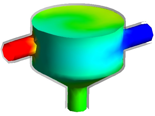
An example of a uniform normal offset of -0.1 [m] to the Default surface of the static mixer,
colored by Temperature, is shown in the diagram.
Distance is available only if the Uniform option is selected. The Distance setting specifies an offset distance, whether it is translational
or normal.
Variable is available only if the Variable option is selected. The Variable setting specifies a variable to plot.
When the distance is described by a variable, you can also incorporate
the variable into an expression. For example, after you have chosen
a variable you can click in the Distance box
and amend it with valid CFX Expression Language (CEL) (for example, 0.5 * Temperature).
Direction is available only if the Translational option is selected. The Direction setting selects a direction to offset the User Surface. Increased
values do not increase the translational offset, they merely change
the ratio that the offset X, Y, and Z directions are placed at. For
example, [2,3,1] and [4,6,2] would identically offset the User Surface.
The Specify Associated Boundary check box
is available only if the ANSYS option is selected.
This setting is also available in an import menu. For details, see Import Mechanical CDB Surface.
The color settings can be changed by clicking the Color tab. For details, see Color Tab.
The rendering settings can be changed by clicking the Render tab. For details, see Render Tab.
The View tab is used for creating or applying predefined Instance Transforms for a wide variety of objects.
For details on changing the view settings, see View Tab.