The input file in AqwaWave must include:
The project name of the structural model to be processed. This should be compatible with the name used in the structural definition file.
The names of the structural data file that defines the model.
The identifier used for the Aqwa model database.
The load generation details.
SYSTEM DATA AREA memory
JOB NEW LINE
PROJECT pname
EXTENSION ext
END
STRU datatype filename
HYDR datatype aqwaid
END
AqwaID aqwaop
CURR
current data
END
LOAD
load case data
END
FELM
finite element program data
END
ASGN
assignment data
END
STOP
The function of this data is to define the overall administration parameters of the analysis.
To define the amount of memory used for data for this run. This is optional, but it may be required for larger structural models.

Parameters:
| SYSTEM | keyword |
| DATA AREA | keyword |
| memory | amount of memory (in integer words) to be used by this run |
Defines the type of analysis to be undertaken and whether to create a new project database for the run. This command is compulsory.

Parameters:
| JOB | keyword |
| status | NEW: Defines that a new project database is to be created. Always used for AqwaWave analysis. |
To define the project name for the current run:

Parameters:
| PROJECT | keyword |
| pname | Project name for the current run. Must correspond with the project name defined for the structural data. |
When processing Ansys structural models, a load input file is generated that may then be used to read the resulting load files into Mechanical APDL. This command specifies the file extensions used when outputting this file.

Parameters:
| EXTE | keyword |
| extension | three letter extension |
Note: The load input file is formed using extension. If
omitted, the file will have the extension .dat on the input
structural data file name. This must not conflict with the extension of the original
data files.
The first part of the AqwaWave data file after the preliminary control data consists of the structural data file name, which define the structural model to be loaded, together with a command defining the hydrodynamic model.
The STRU command is used for defining the structural model.
Parameters:
| STRU | Keyword to denote definition of structural data file |
| prog | Identifier of structural model definition as follows (optional):
|
| filename | Name of a file residing in the current directory containing structural data pertaining to the structural analysis (alphanumeric, up to 32 characters) |
Note:
See Generating Structural FEM Data for Mechanical APDL for creating the required data format when using Mechanical APDL structural models
The data file name must be provided in the correct case on machines that are case sensitive
Refer to Neutral Structural Input File for details of the neutral structural file format
If the file name contains a space, the specified name must be embedded in double quotes (").
The HYDR command defines the hydrodynamic model.

Parameters:
| HYDR | Keyword to denote definition of the hydrodynamic model |
| prog | Identifier of hydrodynamic analysis program as follows (optional):
|
| filename | For Aqwa, this is the name of the Aqwa model to be processed. This is the name associated with the .RES file generated by Aqwa-Line without the extension. For NEUT, this is the name of a file residing in the current directory containing hydrodynamic data pertaining to the hydrodynamic analysis (alphanumeric, up to 32 characters) |
Note:
The data file names need to be provided in the correct case on machines that are case sensitive.
Only one hydrodynamic model definition is allowed within a job.
For the Aqwa option, the model database files (.res, .pot, .uss, and .vac) must use the name given by the filename.
Refer to Neutral Hydrodynamic Input File for details of the neutral hydrodynamic file format.
If the file name contains space, the specified name must be embedded in double quotes (").
This defines any analysis options related to the load generation. This command is compulsory.

Parameters:
| AQWAID | Keyword |
| aqwaop | Analysis options (optional). Valid options are:
|
Note: This command must be provided, even if no analysis options are selected. AQWAID on its own is a valid definition.
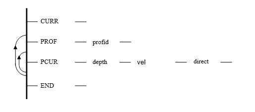
This data contains information on current profiles for combination with wave particle kinematics. This data block can be omitted if the effect of current is to be ignored.

Parameters:
| CURR | Compulsory header to define the start of current definition data |
| PROF | Command keyword for profile creation |
| profid | Profile identifier (Integer, >0) |
| PCUR | Command keyword for point current values |
| depth | Depth measured downwards from SWL (real) |
| vel | Current velocity (real) |
| direct | Direction in degrees (real) |
| END | Compulsory keyword to denote the end of data block |
Notes for PROF command
The profile identifier is referenced by the LOAD definition on successive CASE data records. The profile is defined by successive PCUR data until the next PROF command, or the end of the data block.
Up to ten profiles can be created in each run of AqwaWave.
Notes for PCUR command
The depth is measured downwards from the still water level (SWL). Values of velocity and direction are linearly interpolated between depths. Depths should be strictly increasing on successive data records.
The velocities are always horizontal, in the direction and at the depth specified.
The direction is measured is degrees, positive in the sense of moving from the Aqwa global X-axis to the Aqwa global Y-axis.
Up to ten point current values may be specified for each profile.
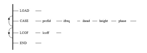
This definition specifies which load cases from Aqwa-Line are required to be transferred to the structural model. This data block is compulsory.

Parameters:
| LOAD | Compulsory header to define the start of load case definition data |
| CASE | Command keyword for load case definition |
| profid | Current profile identifier defined in the CURR data, 0 if no current (integer) |
| ifreq | Wave frequency number (integer) |
| ihead | Wave heading direction number (integer) |
| height | Wave height (real) |
| phase | Wave phase in degrees (real) |
| LCOF | Command keyword for load case offset definition |
| lcoff | Offset which is added to load case numbers produced by AqwaWave. Default is 1000 (integer) |
| END | Compulsory keyword to denote the end of data block |
Notes for CASE command
The current profile number references profiles set up in the CURR data block.
The wave frequency number is defined in Data Category 6 of the preceding Aqwa-Line run and identifies the particular wave frequency to which the floating body is subjected.
The wave heading direction number is defined in Data Category 6 of the preceding Aqwa-Line run and identifies the heading angle of the wave relative to the Aqwa global X-axis. NB: Wave cases must be ordered, first by frequency number (increasing), and then by direction number (increasing).
The wave height, not wave amplitude, is input.
A positive phase defines a wave whose crest passed over the structure center of gravity (T*phase/360) seconds ago, where T is the wave period.
For neutral load output, the phase data is ignored and the real and imaginary load results will always be generated. Refer to Load Results File for details.
Note: The LCOF command (optional) is used to add an offset to the load case numbers produced by AqwaWave. This allows you to create further load cases, by running AqwaWave again, without creating duplicate load case numbers.
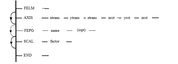
This definition controls the information pertaining to linkage of the finite element program and Aqwa. This data block is optional.

Parameters:
| FELM | Compulsory header to define the start of finite element program information |
| AXIS | Command keyword for defining the structural axis system relative to the Aqwa axis system |
| xtran | X coordinate of the FE Structural Axis origin from the Aqwa Structural Axis origin. (Real) |
| ytran | Y coordinate of the FE structural Axis origin from the Aqwa Structural Axis. (Real) |
| ztran | Z coordinate of the FE Structural Axis origin from the Aqwa Structural Axis origin. (Real) |
| xrot | Roll rotation of the FE Structural Axes for the Aqwa Structural Axes in degree. (Real) |
| yrot | Pitch rotation of the FE Structural Axes from the Aqwa Structural Axes in degrees. (Real) |
| zrot | Yaw rotation of the FE Structural Axes from the Aqwa Structural Axes in degrees. (Real) |
| FEPG | Command keyword to define the finite element package that the loads are generated for |
| name | Name of the finite element package
|
| iopt | Finite element option, applicable to Ansys Mechanical APDL only (integer): |
| SCAL | Command keyword to define conversion factor from structural length units to Aqwa length units |
| factor | Conversion factor from structural length units to Aqwa length units for coordinates data. (Real) |
| END | Compulsory keyword to denote the end of data block |
Notes for AXIS command:
The AXIS card is only required if the co-ordinate system used to define the Aqwa structure is not identical to the structural coordinate system
The translation defines the origin of the FE structural axis system from the origin of the Aqwa fixed reference axes (used to define the Aqwa structure), in Aqwa length units
The rotations of the FE structural axes from the Aqwa fixed reference axes are in degrees. The rotations are applied in the order roll, pitch, yaw (where roll, pitch, and yaw are defined as rotations about the Aqwa fixed reference axes X, Y, and Z respectively).
Notes for FEPG command:
If the input file format is neutral, the output will always be given in neutral format irrespective of the name specified in the FEPG data. Currently, neutral output format is not available for non-neutral input files.
Refer to Load Results File for details of the neutral output file format.
For Mechanical APDL with iopt=1 it is assumed that the cubic option is used for the beam elements, such as KEYOPT(3) = 3
Notes for SCAL command:
The SCAL command is only required if the structural length units are different from the Aqwa length units.
The scale factor is used to multiply the structural coordinates to convert them from structural length units to Aqwa length units. For example, if the FE model units were feet and the Aqwa units were meters, then the appropriate scale factor would be 0.3048.
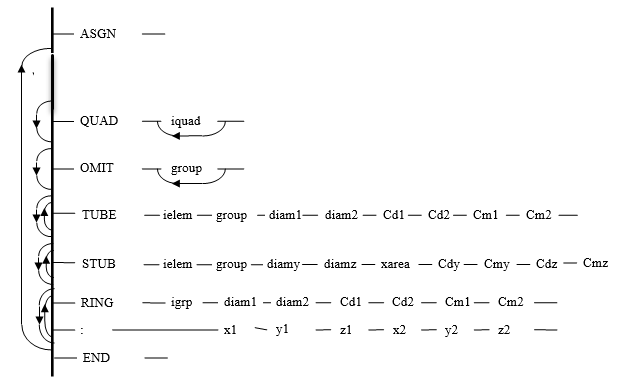
This definition block defines the correlation between the Aqwa and the FE model data and allows hydrodynamic coefficients to be assigned to FE elements.
This block is not needed if you simply want to transfer pressures to a shell or brick model, and does not wish to calculate additional drag loads.
The TUBE, STUB, and RING data records allow coefficients to be set for selected nodes, elements or groups of elements in the FE model.
QUAD data records are used to define which quadrants (or halves) of a symmetric Aqwa model are currently selected. As Aqwa element groups are numbered only in the definition quadrant, the use of the QUAD card allows you to reference corresponding element groups in other quadrants.
OMIT data records are used ONLY if you wish to calculate drag loads on large, cylindrically symmetrical, Aqwa components, which have already been modeled in Aqwa-Line by means of panel elements.
The OMIT data record effectively defines an Aqwa component by specifying all the Aqwa element groups which constitute it. (In general, QUAD data records will also be needed to fully specify the component.) The component remains selected, and loads can be calculated for sections of it, using TUBE, STUB or RING cards (see below), until another Aqwa component is defined.
The purpose of the OMIT data record is to instruct the program to OMIT all the hydrodynamic sources associated with the elements of the component, when calculating drag loads.
OMIT and QUAD data records may be interspersed as required in the data. Several OMIT data records can be specified to provide a long list of groups. OMIT data records are only cumulative in this way when they are consecutive in the data. When separated by other data records, only the selections on the latest data records are applied. Thus, an OMIT data record on its own with no parameters would revert to using the whole Aqwa model, the default at the start of the ASGN definition block. Groups of OMIT data records continue to apply to successive data until a further group is specified.

Parameters:
| ASGN | Compulsory header to define the start of assignment data |
| QUAD | Command keyword to define the quadrant(s) to be considered |
| iquad | Up to 4 quadrant numbers (1 to 4) (integer). |
| OMIT | Command keyword to define the quadrant(s) to be considered |
| group | A list of Aqwa group numbers to be omitted. The groups specified as being omitted will remain so until a further OMIT command is given (integer). |
| TUBE | Command keyword to define the hydrodynamic properties on an FE beam/tube element |
| ielem | Structural tube or beam user element number (integer) |
| group | Aqwa group number whose facets are associated with the beam element. Specify 0 if incident/diffracted forces are not required on this element (integer). One Aqwa group of panel elements can only be associated with one TUBE element or one STUB element. |
| diam1 | Diameter at end 1 of the element (real) |
| diam2 | Diameter at end 2 of the element (real) |
| Cd1 | Drag coefficient at end 1 of the element (real) |
| Cd2 | Drag coefficient at end 2 of the element (real) |
| Cm1 | Inertia coefficient at end 1 of the element |
| Cm2 | Inertia coefficient at end 2 of the element |
| STUB | Command keyword to define the hydrodynamic properties on a beam/tube element |
| ielem | F.E. tube or beam user element number (integer) |
| group | Aqwa group number whose facets are associated with the beam element. Specify 0 if incident/diffracted forces are not required on this element (integer). One Aqwa group of panel elements can only be associated with one STUB element. |
| diamy | Effective Y diameter of the element (real) |
| diamz | Effective Z diameter of the element (real) |
| xarea | Cross-sectional area of the element (real) |
| Cdy | Y drag coefficient of the element (real) |
| Cmy | Y inertia coefficient of the element (real) |
| Cdz | Z drag coefficient of the element (real) |
| Cmz | Z inertia coefficient of the element (real) |
| RING | Command keyword to define the hydrodynamic properties on a ring of elements |
| igrp | Structural group number for the elements that form a ring (or part ring) in the FE model (integer) |
| diam1 | Diameter at end 1 of the ring axis (real) |
| diam2 | Diameter at end 2 of the ring axis (real) |
| Cd1 | Drag coefficient at end 1 of the ring axis (real) |
| Cd2 | Drag coefficient at end 2 of the ring axis (real) |
| Cm1 | Inertia coefficient at end 1 of the ring axis (real) |
| Cm2 | Inertia coefficient at end 2 of the ring axis (real) |
| x1 | X coordinate at end 1 of the ring axis (real) |
| y1 | Y coordinate at end 1 of the ring axis (real) |
| z1 | Z coordinate at end 1 of the ring axis (real) |
| x2 | X coordinate at end 2 of the ring axis (real) |
| y2 | Y coordinate at end 2 of the ring axis (real) |
| z2 | Z coordinate at end 2 of the ring axis (real) |
Note: If necessary, additional data for a command may be specified using the continuation symbol, colon (:)
Notes for QUAD command:
The quadrant numbers are designated 1-4. For a singly symmetric structure, only halves 1 and 2 are available. If symmetry has not been used, only one quadrant is defined.
Quadrant 1 is always the modelled quadrant and quadrant 2 is the mirror of this for singly symmetric structures. For doubly-symmetric models, the following is the case:
Quadrant 2 is the mirror of the model about the Y-axis
Quadrant 3 is the mirror of the model about the X-axis
Quadrant 4 is the diagonally opposite quadrant
All subsequent Aqwa-Line group definitions on OMIT, RING, and TUBE commands will refer to the selected quadrant or quadrants until another QUAD data record appears to redefine this. At the start of the assignment data, all possible quadrants are active.
Notes for OMIT command:
The group(s) specified as being OMITted will remain so until a further OMIT command or group of commands is given.
OMIT commands are used to specify the Aqwa element groups that make up the component (for example, GBS shaft) in sections that you want drag loads to be calculated. Subsequent TUBE and RING data records relate to this component. The specified element groups are omitted in the calculation of fluid flow. The AqwaWave program is then able to calculate the correct effective flow 'seen by' the TUBE and RING sections, as required by Morison's equation. If you do not omit these groups, the diffracted component of the flow calculated by the program will be erroneous.
OMIT commands only define that part of the Aqwa component which is in the definition quadrant. QUAD commands may also be needed to define the complete component.
Notes for TUBE command:
The beam/tube element on the currently selected component will be loaded.
The group of Aqwa panels relates to all selected quadrants. Incident/diffracted forces on the selected groups of facets will be summed and applied as global distributed loads to the selected element. Note that, in general, the inertia coefficients should be zero if the incident/diffracted forces are transferred, as both relate to the same effect.
The hydrodynamic properties can be different in the element local y and z directions. These properties are, however, constant along the beam.
Inertia coefficient (Cm) is defined by Cm = Ca + 1, where Ca is the added mass coefficient.
TUBE and STUB commands should not be applied to the same element or else the hydrodynamic loads may be duplicated.
Notes for STUB command:
The beam/tube element on the currently selected component will be loaded.
The group of Aqwa panels relates to all selected quadrants. Incident/diffracted forces on the selected groups of panels will be summed and applied as global distributed loads to the selected element. Note that, in general, the inertial coefficients should be zero if the incident/diffracted forces are transferred, as both relate to the same effect.
The hydrodynamic properties can be different in the element local y and z directions. These properties are, however, constant along the beam.
Inertia coefficient (Cm) is defined by Cm = Ca + 1, where Ca is the added mass coefficient.
TUBE and STUB commands should not be applied to the same element or else the hydrodynamic loads may be duplicated.
Notes for RING command:
The diameters may be different at the two ends and may differ from the structural diameter (for marine growth, for instance).
The inertia coefficients (Cm) would normally be zero, as inertia loads would be provided by incident/diffracted forces except above the still water level (SWL). Where provided, they are defined by Cm = Ca + 1.
If a RING is above the SWL and on which inertia and drag loads are to be calculated and transferred to the structural model, the faces on this RING should then be defined in load case 1000 as if they are on the wetted faces. The wave pressures from Aqwa will not be transferred to these nodes when their z coordinate is greater than zero.
End coordinates of the axis of the ring are defined in Aqwa structure definition axes (as given in the Aqwa node coordinate information, COOR).
The following is an example of an ASGN data for AqwaWave:
          ASGN
      TUBE    1     0     1.20      1.20       0.7       0.7       1.5       1.5
      TUBE    3     0     1.20      1.20       0.7       0.7       1.5       1.5
      TUBE    5     0     1.25      1.25       0.7       0.7       1.5       1.5
      OMIT    3    5
      TUBE  162    3      5.90      6.15       1.0       1.0       0.0       0.0
      TUBE   71    5      5.65      5.90       1.0       1.0       0.0       0.0
      QUAD    1
      OMIT   10   11   12   13   14   15
      RING  111           6.15      6.40       1.0       1.0       0.0       0.0
     :                    15.00     15.00     79.00     15.00     15.00     74.00
      RING  112           6.40      6.65       1.0       1.0       0.0       0.0
     :                    15.00     15.00     74.00     15.00     15.00     69.00
      RING  113           6.65      6.80       1.0       1.0       0.0       0.0
     :                    15.00     15.00     69.00     15.00     15.00     64.00
      END
The first three TUBE data records assign diameters, drag and mass coefficients to beam type elements in the final structure, the default at the start of the data. The members are not represented in the Aqwa-Line run by facets, as the Aqwa group field is blank. Inertia coefficients are supplied instead.
The next section requests two further tubes are loaded, this time taking incident/diffracted forces from Aqwa groups and having no inertia forces. The OMIT command removes the effort of the Aqwa panels associated with these groups from modifying the fluid flow, as required for Morison's equation.
Finally, quadrant 1 is selected (the unmirrored half in a single symmetric model). After omitting several Aqwa groups from this quadrant, three rings (groups 111, 112, and 113 in the structural mode) are defined and will be loaded. These loads will include drag loading if a current has been defined.


