- Mechanical APDL Function
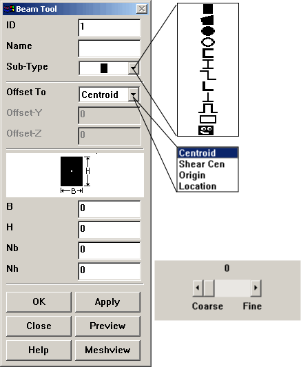
Use the BeamTool to create beam cross sections. You may select a predefined cross section shape or define an arbitrary shape.
- ID
The ID number of the cross section [SECTYPE].
- Name
The name of the cross section, 8 alphanumeric characters maximum [SECTYPE].
- Sub-Type
The cross section subtype. Clicking the Sub-Type button displays a drop-down list of predefined shapes.
RECT creates a rectangular cross section.
QUAD creates a quadrilateral cross section.
CSOLID creates a circular solid cross section.
CTUBE creates a circular hollow cross section.
CHAN creates a U-shaped cross section.
I creates an I-shaped cross section.
Z creates a Z-shaped cross section.
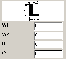
L creates an L-shaped cross section.
T creates a T-shaped cross section.
HATS creates a hat-shaped cross section.
HREC creates a hollow rectangular cross section.
ASEC creates a user-defined shape for a cross section.
- Section Offsets
- Offset To
The section offset for the cross section [SECOFFSET]. Selecting the Offset To button displays a drop-down list with the following options:
Centroid: Beam node will be offset to centroid (default).Shear Cen: Beam node will be offset to Shear Center.Origin: Beam node will be offset to origin of the cross section.Location: Beam node is offset to the user-specified location set in the Offset-Y and Offset-Z fields:
- Offset-Y, Offset-Z
Values that locate the node with respect to the default origin of cross section when the
Locationoption is chosen.
- Section Shape
The shape of the cross section.
- Dimension Labels
Geometry information for each dimension [SECDATA]:
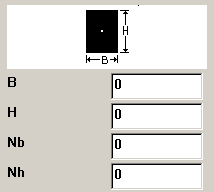
Rectangular Cross Section Dimensions B = Width
H = Height
Nb = Number of cells along width, default = 2
Nh = Number of cells along height, default = 2
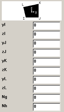
Quadrilaterial Cross Section Dimensions yI, zI, yJ, zJ, yK, zK, yL, zL = Coordinate location of various points
Ng = Number of cells along g, default = 2
Nh = Number of cells along h, default = 2
Note: Degeneration to triangle is permitted by specifying the same coordinates for nodes along an edge.
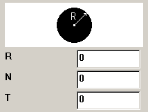
Circular Solid Cross Section Dimensions R = Radius
N = Number of divisions along the circumference
T = Number of divisions through the radius
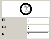
Hollow Circular Cross Section Dimensions Ri = Inner radius of the tube
Ro = Outer radius of the tube
N = Number of cells along the circumference; default = 8
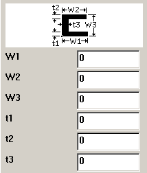
Channel Cross Section Dimensions W1, W2 = Lengths of the flanges
W3 = Overall depth
t1, t2 = Flange thicknesses
t3 = Web thickness
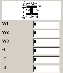
I-shaped Cross Section Dimensions W1,W2 = Width of the top and bottom flanges
W3 = Overall depth
t1,t2 = Flange thicknesses
t3 = Web thickness
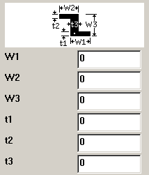
Z-shaped Cross Section Dimensions W1,W2 = Flange lengths
W3 = Overall depth
t1,t2 = Flange thicknesses
t3 = Stem thickness
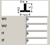
T-shaped Cross Section Dimensions W1 = Flange width
W2 = Overall depth
t1 = Flange thickness
t2 = Stem thickness
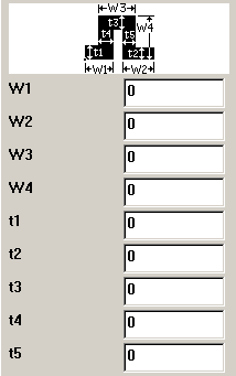
Hat-shaped Cross Section Dimensions W1,W2 = Width of the brim
W3 = Width of the top of the hat
W4 = Overall depth
t1,t2 = Thickness of the brim
t3 = Thickness of the top of the hat
t4,t5 = Web thicknesses
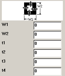
Hollow Rectangular Cross Section Dimensions W1 = Outer width of the box
W2 = Outer height of the box
t1, t2, t3, t4 = Wall thicknesses
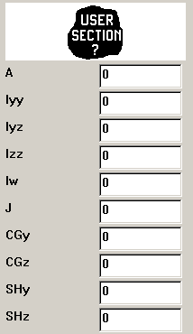
Arbitrary Cross Section Dimensions A = Area of section
Iyy = Moment of inertia about the y axis
Iyz = Product of inertia
Izz = Moment of inertia about the z axis
Iw = Warping constant
J = Torsional constant
CGy = Y coordinate of centroid
CGz = Z coordinate of centroid
SHy = y coordinate of shear center
SHz = z coordinate of shear center
The SECPLOT command cannot display the plot of an arbitrary section (ASEC) subtype. However, consider issuing the /ESHAPE command to display the orientation of the section.
- Mesh Refinement
Sets mesh refinement level for thin-walled sections. Values are 0 (the default - no mesh refinement) to 5 (high level of mesh refinement).
- Action Buttons
: Displays a sample cross section using the specified shape and dimension information without applying this information to the database.
: Same as except section mesh is also displayed.

