Benchmark C8
VMC8
Aluminum Bar Impacting a Rigid Boundary
Overview
Test Case
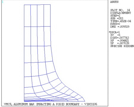
A cylindrical aluminum bar impacts a rigid wall at a velocity Vo. Determine the deformed length of the bar and perform axisymmetric analyses with the element types noted above.

| Material Properties | Geometric Properties | Loading | ||||||||
|---|---|---|---|---|---|---|---|---|---|---|
|
|
|

Assumptions, Modeling Notes, and Solution Comments
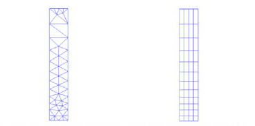
The test case is modelled as a 2D axisymmetric analysis with elements PLANE182 and PLANE183. Each analysis consists of two load steps. The first load step is static and serves to define the initial velocity. The second load step resolves the nonlinear transient effects.
The material behavior is assumed to be elastic perfectly plastic and obey a bilinear isotropic hardening law. The elastic wave propagation speed is defined as
 . The time required for the elastic
wave to travel across a typical element in the radial direction is
used to define the minimum number of substeps. A time span of 4.5
x 10-5 seconds allows the bar to impact
and realize its maximum deflection. Auto time stepping (AUTOTS) is used to control the time step increments. The
large deflection effects are included using NLGEOM. Solution efficiency is improved by relaxing the convergence criteria
(CNVTOL).
. The time required for the elastic
wave to travel across a typical element in the radial direction is
used to define the minimum number of substeps. A time span of 4.5
x 10-5 seconds allows the bar to impact
and realize its maximum deflection. Auto time stepping (AUTOTS) is used to control the time step increments. The
large deflection effects are included using NLGEOM. Solution efficiency is improved by relaxing the convergence criteria
(CNVTOL).In comparison, the plane and solid elements perform equally well as the viscoplastic elements for the strain levels encountered in this problem. Introducing a rate-dependent material property to the problem would illustrate advantage to viscoplastic elements.
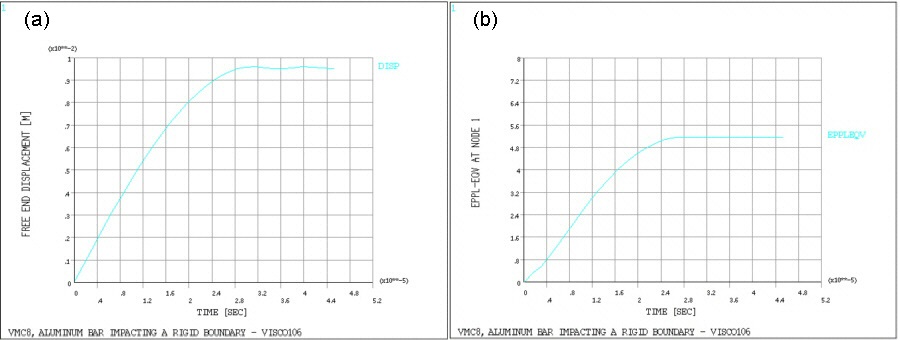
Using POST26, plots of the displacement vs. time (Figure 602: Deformed Shape) and equivalent plastic strain (Figure 603: Time History Graphs - for the center node on the impact face) vs. time are produced.