VM291
VM291
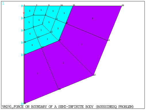
Force on the Boundary of a Semi-Infinite Body (Boussinesq
Problem)
Overview
Test Case
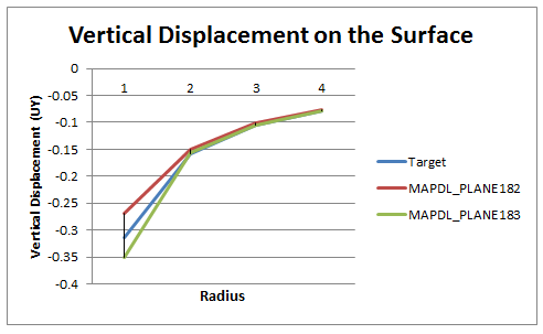
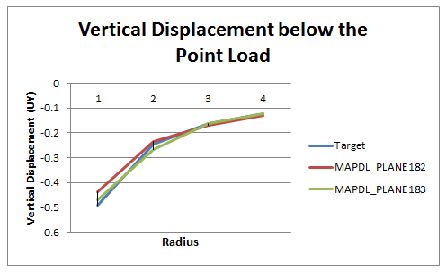
A point force is applied at the origin of a half-space 2D axisymmetric solid modeled with far-field domain. Determine the displacement in the Y-direction on nodes along the radial direction (at location Y = 0) and vertical direction (at location X = 0).

Analysis Assumptions and Modeling Notes
The problem is solved for two cases:
The problem is composed with 12 axisymmetric finite element mesh (PLANE182 or PLANE183) with a radius of 4 from the origin, and 4 infinite element mesh (INFIN257) modeling the far-field domain with a radius of 4 extending from the finite element domain. The infinite element mesh is modeled using the EINFIN command. The UX degrees of freedom are constrained at location X = 0. The UY results are computed along the radial and vertical direction on the nodes belonging to the finite element mesh and then compared to the analytical results.
The analytic solution to compute vertical displacement for the problem of a point load on a half space is:

Where  is the point load,
  is the Young’s
modulus,
is the Young’s
modulus,  is the Poisson’s ratio,
and
is the Poisson’s ratio,
and  and
and  are the radial and
vertical distance from the point load. The above equation clearly
shows the
are the radial and
vertical distance from the point load. The above equation clearly
shows the  singularity at the point of application
of the load (
singularity at the point of application
of the load ( and
and  ), which indicates that the finite element results
may not be close to the analytical solution a points close to the
origin.
), which indicates that the finite element results
may not be close to the analytical solution a points close to the
origin.
Results Comparison
| Using PLANE182 and INFIN257 Elements | ||||
|---|---|---|---|---|
| Node Number | Target | Mechanical APDL | Ratio | |
| Vertical displacement (UY) on the surface (Y = 0) | 5 | -0.1576 | -0.1504 | 1.048 |
| 10 | -0.1050 | -0.1009 | 1.041 | |
| 15 | -0.0788 | -0.0771 | 1.021 | |
| Vertical displacement (UY) below the point load (X = 0) | 9 | -0.2451 | -0.2351 | 1.042 |
| 14 | -0.1634 | -0.1688 | 0.968 | |
| 19 | -0.1225 | -0.1292 | 0.949 | |
| Using PLANE183 and INFIN257 Elements | ||||
| Node Number | Target | Mechanical APDL | Ratio | |
| Vertical displacement (UY) on the surface (Y = 0) | 10 | -0.1576 | -0.1575 | 1.001 |
| 23 | -0.1050 | -0.1058 | 0.993 | |
| 37 | -0.0788 | -0.0787 | 1.002 | |
| Vertical displacement (UY) below the point load (X = 0) | 19 | -0.2451 | -0.2663 | 0.920 |
| 33 | -0.1634 | -0.1619 | 1.010 | |
| 47 | -0.1225 | -0.1225 | 1.000 | |