VM240
VM240
Thermal Expansion of Rigid Beams in a Composite Bar
Test Case
A composite bar consists of two base materials with 25 rigid beams embedded along its length. A coefficient of thermal expansion is defined for only the rigid beams. Compare the stresses resulting in both solid composite materials when a temperature is applied.

Analysis Assumptions and Modeling Notes
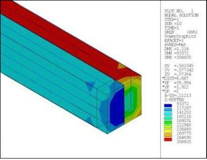
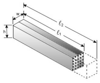
A composite bar with a 4" x 4" cross-section is modeled using SOLID185 elements. The bar consists of two different materials with the material properties E1, E2, υ1, and υ2 as shown above. Twenty five MPC184 rigid beam elements are then modeled running along the length of the bar. The rigid beam elements are given a coefficient of thermal expansion, α 3. The bar is fixed in all DOF’s at one end. As a temperature is applied to the model, the rigid beam elements expand, in turn deforming the rest of the composite bar. As a result, two distinctly different stress levels can be seen through the bar’s cross-section. These stresses reflect the material property differences of the two materials making up the composite
The equations below are used to calculate theoretical stress values for comparison: