VM239
VM239
Mechanics of the Revolute and Universal Joints
Overview
Test Case
A double universal joint drive shaft drives a simple slider-crank mechanism. Compare the rotations at different points in the drive shaft with the applied rotation. Also, show the linear motion caused by the slider-crank satisfied the appropriate equation.

| Material Properties | Geometric Properties | Loading | ||||||||
|---|---|---|---|---|---|---|---|---|---|---|
|
|
|
Analysis Assumptions and Modeling Notes
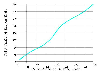
The rotation of 2π rad., which is applied at node "a", is first transmitted through the three shafts, existing in the x-y plane, that are joined together by the MPC184 universal joints. The rotation is compared with the resulting rotation at node "c". This graph should result in an expression determined by the following function:
α2 = arc tan (tanα 1/cosβ)
where:
| α1 = the angle of twist of the drive shaft |
| α2 = the angle of twist of the driven shaft |
| β = relative angle between axis of rotation of the shafts |
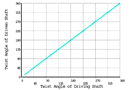
The input rotation is next compared to the resulting rotation at node "d". The plot shows a linear relationship in which the rotations at "a" should be equal to the rotations at "d". It should be noted that the revolute joint at junction "e" is tested by comparing the results of the input rotation at "a" (which is transferred perfectly to "d") with the linear, sliding motion generated by the slider-crank mechanism lying in the y-z plane. This relationship is defined in the supplied reference, and reflected below in the results.
Two solutions are performed. The first solution is performed by modeling all links as flexible using BEAM188 beam elements. The second solution is performed by modeling all links as rigid using MPC184 elements with Rigid Beam with Lagrange Multiplier Reduction Method characteristics. The second solution demonstrates how to define rigid bodies in Mechanical APDL and how to prevent over-constrained models. Both solutions produce similar expected results.
Results Comparison
Input Rotation vs. Linear Motion of Slider-Crank Mechanism
| Applied Rotation | Target | Mechanical APDL | Ratio |
|---|---|---|---|
| Results for analysis with all flexible bodies | |||
| Linear Motion (x) for π/4 (45°) | 0.39708 | 0.39708 | 1.0 |
| Linear Motion (x) for π/2 (90°) | 0.58579 | 0.58579 | 1.0 |
| Linear Motion (x) for 3π/4 (135°) | 0.39708 | 0.39708 | 1.0 |
| Results for analysis with all rigid bodies | |||
| Linear Motion (x) for π/4 (45°) | 0.39708 | 0.39708 | 1.0 |
| Linear Motion (x) for π/2 (90°) | 0.58579 | 0.58579 | 1.0 |
| Linear Motion (x) for 3π/4 (135°) | 0.39708 | 0.39708 | 1.0 |