VM232
VM232
Stress Intensity Factor for a Single Edge Crack with Pressure Load Using UMM
Method
Overview
| Reference: | Stephens, R.I., Fatemi, A., Stephens, R.R., Fuchs, H.O., Metal Fatigue in Engineering, 2nd Edition, 2006, pg. 130 |
| Analysis Type(s): | Static Analysis (ANTYPE = 0) |
| Element Type(s): |
3D 8-Node Structural Solid Element (SOLID185) 3D 20-Node Structural Solid Element (SOLID186) 3D 10-Node Structural Solid Element (SOLID187) |
| Input Listing: |
VM232 requires a supplemental .cdb input file which is too long to include full input listings. This file must be downloaded and placed in your working directory for the test case to run properly. Additionally, the geometry and mesh should be regenerated. Download link: MAPDL Test Case Files for 2024 R2 vm232-1.cdb vm232-2.cdb vm232-3.cdb |
Test Case
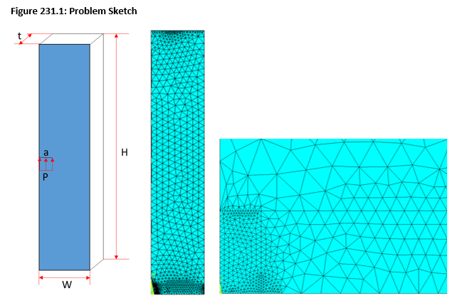
A solid block with width W = 1 m, height H = 5 m, and thickness t = 0.1 m is modeled with a single edge crack of length a = 0.1 m. The crack is subjected to a pressure load P and the stress intensity factor is determined using the UMM method (CINT,UMM,ON). The results are compared to the analytical solution given in the reference (point b in table 6.1, pg. 130).
| Material Properties | Geometric Properties | Loading | ||||||
|---|---|---|---|---|---|---|---|---|
|
| Pressure, P = 5 x 10⁹ Pa |
Analysis Assumptions and Modeling Notes
The analysis is solved by meshing the block with tetrahedral SOLID185 elements, tetrahedral SOLID186 elements, and SOLID187 elements. Only half of the geometry is modeled and the symmetry boundary condition is used to resemble a crack halfway along the length of the block. Pressure is applied to the crack surface using the SF command. Stress intensity factor for the crack tip node is computed using CINT commands. The result is compared to the stress intensity factor (KI) obtained from the following equation:
where
The problem is solved with degenerated mesh to verify the accuracy of the UMM method in computing the fracture parameters.


