VM185
VM185
AC Analysis of a Slot Embedded Conductor
Overview
Test Case
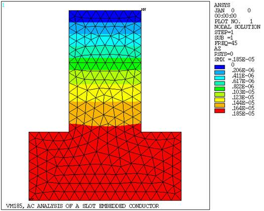
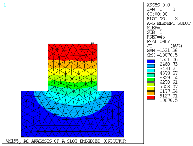
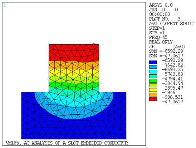
A solid copper conductor embedded in the slot of an electric machine carries a current I at a frequency ω. Determine the distribution of the current within the conductor, the source current density, the complex impedance of the conductor, and the AC/DC power loss ratio.

| Material Properties | Geometric Properties | Loading | ||||||||||
|---|---|---|---|---|---|---|---|---|---|---|---|---|
|
|
|
Analysis Assumptions and Modeling Notes
The slot is assumed to be infinitely long, so end effects are ignored, allowing for a two-dimensional planar analysis. An assumption is made that the steel slot is infinitely permeable and thus is replaced with a flux-normal boundary condition. It is also assumed that the flux is contained within the slot, so a flux-parallel boundary condition is placed along the top of the slot.
The problem requires a coupled electromagnetic field analysis using the VOLT and AZ degrees of freedom. All VOLT DOFs within the copper conductor are coupled together to enforce the correct solution of the source current density component of the total current density. The eddy current component of the total current density is determined from the AZ DOF solution. The current may be applied to a single arbitrary node in the conductor, since they are all coupled together in VOLT.
The complex impedance of the slot is calculated in POST1 from the equation

where V = voltage drop,
 and
and
 are real and imaginary components of the source
current density (obtained from the solution results in the database
file). The real component of the impedance represents the AC resistance
Rac per unit length. The DC resistance per
unit length Rdc is calculated as ρ/A.
The AC/DC power loss ratio is calculated as Rac/Rdc. The problem is solved first using PLANE13 elements then using PLANE233 elements.
are real and imaginary components of the source
current density (obtained from the solution results in the database
file). The real component of the impedance represents the AC resistance
Rac per unit length. The DC resistance per
unit length Rdc is calculated as ρ/A.
The AC/DC power loss ratio is calculated as Rac/Rdc. The problem is solved first using PLANE13 elements then using PLANE233 elements.
Results Comparison
| Target[1] | Mechanical APDL | Ratio | |
|---|---|---|---|
| PLANE13 | |||

| 10183 | 10123.54 | 0.994 |

| 27328 | 27337.36 | 1.000 |
| Impedance (Ohm/m) x 10-6 | 175 + j471 | 175 + j471 | 0.997, 1.001 |
| Loss Ratio | 2.33[1] | 2.387 | 1.025 |
| PLANE233 | |||

| 10183 | 10187.33 | 1.000 |

| 27328 | 27326.18 | 1.000 |
| Impedance (Ohm/m) x 10-6 | 175 + j471 | 176 + j471 | 1.004, 1.00 |
| Loss Ratio | 2.33[1] | 2.40 | 1.031 |