VM184
VM184
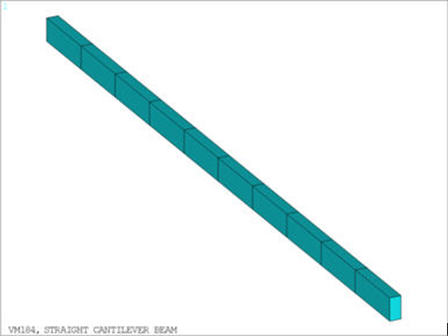
Straight Cantilever Beam
Test Case
A beam of length
 , height
h, and thickness t is built-in at one end and loaded at the free end
with an axial force, an in-plane shear force and an out-of-plane shear
force, all of magnitude F. Determine the deflections δx, δy, and δz at the free end due to these loads.
, height
h, and thickness t is built-in at one end and loaded at the free end
with an axial force, an in-plane shear force and an out-of-plane shear
force, all of magnitude F. Determine the deflections δx, δy, and δz at the free end due to these loads.
Analysis Assumptions and Modeling Notes
The problem is solved in four different ways:
using Coupled-Field Solid Elements (SOLID5)
using Tetrahedral Solid Elements (SOLID92)
using Tetrahedral coupled-Field Solid Elements (SOLID98)
using Tetrahedral Solid Elements (SOLID187)
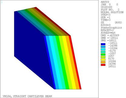
POST1 is used to directly obtain the difference between the theoretical solution and the
Ansys results in the form of a ratio, using the maximum displacement value on the free
face.