VM177
VM177
Natural Frequency of a Submerged Ring
Overview
| Reference: | E. A. Schroeder, M. S. Marcus, "Finite Element Solution of Fluid Structure Interaction Problems", Shock and Vibration Symposium, San Diego, CA, 1975. |
| Analysis Type(s): | |
| Element Type(s): | |
| Input Listing: | vm177.dat |
Test Case
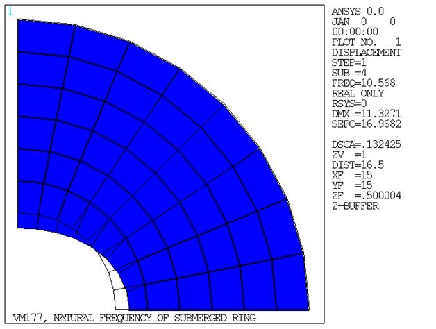
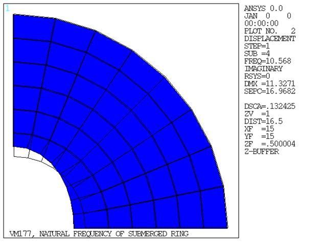
A steel ring is submerged in a compressible fluid (water). Determine the lowest natural frequency for x-y plane bending modes of the fluid-structure system.
| Material Properties | Geometric Properties | |||||||||||
|---|---|---|---|---|---|---|---|---|---|---|---|---|
|
|
Analysis Assumptions and Modeling Notes
For this problem, the fluid is assumed as extending only to
a finite radius b where the pressure Po is
zero and b is taken to be 30 inches. From the reference, this assumption
should result in an error of less than 1% compared to the frequency
for an unbounded fluid (b =
). The natural boundary conditions at the coordinate axes imply
that δP / δx = 0 at x = 0 and δP / δy = 0
at y = 0.
This problem is solved using five separate analyses. The first
uses 3D acoustic fluid elements (FLUID30) with quadrilateral shell
elements (SHELL63), the second uses 2D acoustic
fluid elements (FLUID29) with BEAM188, the third uses 3D acoustic fluid elements
(FLUID30) with quadrilateral shell elements
(SHELL181), the fourth uses 3D 20 node hexahedral
acoustic fluid elements (FLUID220) with 8
node structural shell elements (SHELL281)
and the fifth one uses 3D 10 node tetrahedral fluid elements (FLUID221) with 8 node structural shell elements (SHELL281).
For cases 1, 3, 4, and 5, due to fluid-structure coupling involving unsymmetric matrices, the natural frequency is determined by first performing a modal solve (ANTYPE = 2), and then the first mode is excited by performing a full harmonic (ANTYPE = 3) analysis with a frequency sweep. Monitoring the displacement of key nodes over the frequency range indicates the approximate desired natural frequency as the point where the nodal displacements indicate a resonant condition.
In the second case, the lowest natural frequency is obtained using an unsymmetric matrix modal analysis (ANTYPE = 2) corresponding to the frequency of mode one of the frequency data from the Lanczos unsymmetric eigensolver.
A preliminary finite element analysis (not shown here) was used to estimate a narrow range in which the 1st even bending mode frequency occurs. For cases 1, 3, 4, and 5, two unit loads are arbitrarily used to excite the desired bending mode of vibration.
Results Comparison
| Target[1] | Mechanical APDL | Ratio | ||
|---|---|---|---|---|
| FLUID30 and SHELL63 | f1, Hz | 10.20 | 10.560 < f < 10.580 | 1.036 |
| FLUID29 and BEAM188 | f1, Hz | 10.20 | 10.63 | 1.042 |
| FLUID30 and SHELL181 | f1, Hz | 10.20 | 10.640 < f < 10.660 | 1.044 |
| FLUID220 and SHELL281 | f1, Hz | 10.20 | 10.270 < f < 10.290 | 1.008 |
| FLUID221 and SHELL281 | f1, Hz | 10.20 | 10.33 < f < 10.35 | 1.014 |
Figure 266: Node 1 Displacement vs. Driving Frequency Near 1st Bending Mode Natural Frequency (Full Harmonic Analysis)


