VM171
VM171
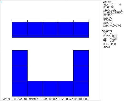
Permanent Magnet Circuit With an Elastic Keeper
Overview
Test Case
A permanent magnet circuit consisting of a highly-permeable core and a permanent magnet is used to model a relay switch. An elastic keeper is modeled with a highly permeable iron and two springs. Assuming no flux leakage, determine the equilibrium displacements, δ, of the keeper and the operating point (flux density) in the permanent magnet.

| Material Properties | Geometric Properties | |||||||
|---|---|---|---|---|---|---|---|---|
|
For permanent magnet:
For iron:
For springs:
For iron and permanent magnet:
|
h = .03 m w = .03 m t = .01 m a = .01 m |
Analysis Assumptions and Modeling Notes
Two analyses are performed: The first uses PLANE13 elements, and the second uses PLANE223 elements. Since no leakage is assumed, the flux path will follow a closed loop through the iron core, permanent magnet, air gap, and keeper. The flux must follow a path parallel to the edges of the device, thus a flux-parallel (A = 0) boundary is set at the external nodes of the model. The inner nodes are coupled to ensure a flux-parallel boundary condition at the inner edge. The iron is assumed to be infinitely permeable and is assigned μr = 105. For a permanent magnet, μoμr = Br /Hc, therefore μr = 5.305. The modulus of elasticity for air is assigned a negligible value (100 N/m2) compared to that of the permeable materials. The permanent magnet structure has its displacements fixed. A magnetic pressure surface is assigned to the elements adjacent to the air-keeper interface to allow for the application of magnetic forces for structural analysis. An iterative large-deflection solution is required. Convergence criteria for structural force and magnetic current-segment is defined.