


To reduce noise in an aircraft cabin, viscothermal quarter-wave resonator panels can be positioned within the cabin. Resonator tube lengths and diameters are optimized to maximize the sound absorption in the frequency range of interest. The resonator model described here is therefore tested experimentally and numerically using the impedance tube method.
The following figure shows the geometry of the resonator model used in this simulation:
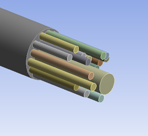
This figure shows the resonator composed of tubes with variable diameters and lengths, resulting in an optimized absorption for all frequencies:
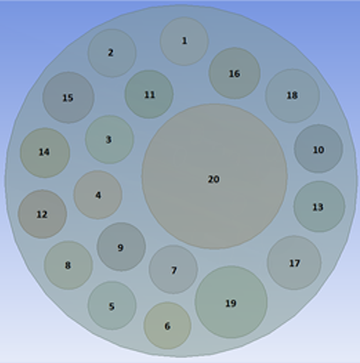
Radii and length for each tube are defined with the following values:[1]
|
Tube Number |
Radius (mm) |
Length (mm) |
|---|---|---|
|
1 |
3.4 |
43.6 |
|
2 |
3.4 |
43.6 |
|
3 |
3.4 |
45.4 |
|
4 |
3.4 |
46.8 |
|
5 |
3.4 |
48.6 |
|
6 |
3.3 |
50.5 |
|
7 |
3.4 |
40.6 |
|
8 |
3.4 |
52.1 |
|
9 |
3.4 |
54.4 |
|
10 |
3.4 |
56.7 |
|
11 |
3.4 |
59.0 |
|
12 |
3.4 |
61.7 |
|
13 |
3.6 |
64.7 |
|
14 |
3.5 |
66.9 |
|
15 |
3.6 |
69.8 |
|
16 |
3.6 |
72.9 |
|
17 |
3.8 |
76.1 |
|
18 |
3.8 |
79.8 |
|
19 |
5.1 |
36.8 |
|
20 |
10.3 |
82.3 |