


Composite T-joints are used in a wide variety of applications, from fuselage stiffeners in aerospace structures to load-transmission joints between the hull and bulkhead in oceangoing vessels.[1]
The following figure shows a typical T-joint geometry:
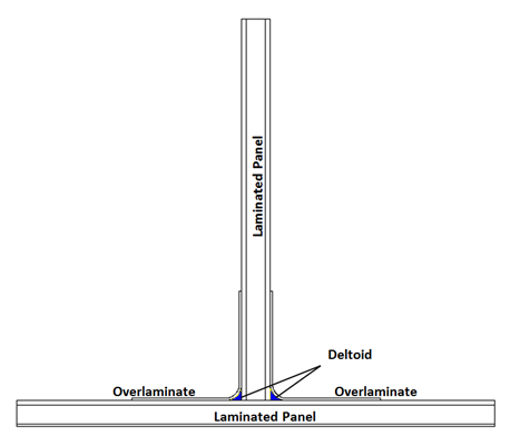
The T-Joint consists of laminated panels connected via composite overlaminates and deltoids (gap fillers).
Because the overlaminates and the deltoid make up the load-transmission path between a vessel’s hull and bulkhead, the strength of the joints depends on the strength of both components. Due to the variable quality of the interfaces and the presence of defects, overlaminates can be the primary source of delamination.[2]
The T-Joint simulation shows delamination propagation under a mechanical pull-off load case using VCCT-based crack-growth. The energy-release-rate calculations using VCCT are based on the assumption that the energy needed to separate a surface is the same as the energy needed to close the same surface, and therefore that the crack-growth criteria is the energy-release rate. Because cracks generally grow along interfaces, VCCT-based crack-growth simulation is an effective technique for simulating interface delamination of laminate composites.