


Two load steps are defined (parts (b) and (c) in Figure 3.2: Sealing System and Finite Element Model).
Loading is applied as follows:
Load Step 1
Ux rigid shaft = 0.2794 mm Ux rigid groove = - 0.05715 mm The housing compression is analyzed in the first load step. The rigid shaft surface (left side) moves 0.2794 mm in the x direction and the rigid groove surfaces (right side) move 0.05715 in the negative x direction, simulating the housing assembly.
Load Step 2
PRES = 4.1 MPa In the second load step, a fluid penetration pressure of 4.1 MPa is applied to the contact pairs (via the SFE command with the load key value
LKEYset to 1), as shown:esel,s,real,,6 ! select rigid-flexible contact pair esel,r,ename,,172 ! reselect contact elements only esel,a,real,,8 ! select flexible-flexible contact pair sfe,all,1,pres,,4.1 ! apply fluid pressure allselThe following input prevents fluid penetration loads from being applied multiple times on overlapping contact elements from different pairs:
esel,s,real,,8                      ! select flexible-flexible contact pair
nsle
esln,s,1
esel,r,real,,6                      ! reselect rigid-flexible contact pair
sfedele,all,all,all                 ! remove overlapping fluid pressure loads
allsel
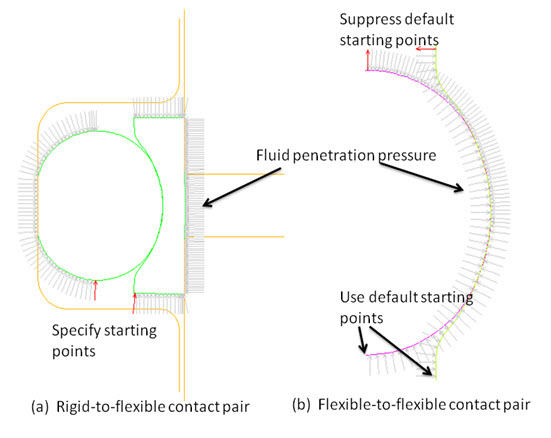
The fluid-penetration starting points are also specified in order to model the system
fluid pressure exposed from the bottom part (the opening between the shaft and the lower
part of groove). For the rigid-to-flexible contact pair, no default starting points
exist because the contact surfaces are in a closed loop, as shown in (a). To activate
the fluid penetration pressure, two contact elements are chosen as starting points
initially exposed to the fluid (via the SFE command, with the load
key value LKEY set to 2 and the first starting point status
value VAL1 set to 1), as follows:
SFE,3121,2,PRES,,1				! starting point for o-ring
SFE,3308,2,PRES,,1				! starting point for cap
One starting point is for the contact surface of the o-ring, and the other is for the contact surface of the cap, respectively.
For the flexible-to-flexible contact pair, the ending points of the contact and target
surfaces are the default starting points. To force the fluid to penetrate from the
bottom only, the two default starting points on the top part of the seals are suppressed
(via the SFE command, with the load key value
LKEY set to 2 and the first starting point status value
VAL1 set to -1), as follows:
SFE,2529,2,PRES,,-1
SFE,2625,2,PRES,,-1