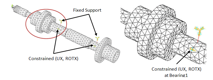
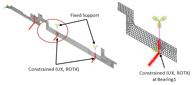
Fixed support conditions are applied to the second node of the bearing elements, as shown in the figure below. Translational and rotational DOFs about the axis of rotation at the bearing locations are constrained.
The effect of the unbalanced mass on the disk is represented by forces acting in the two directions perpendicular to the spinning axis. The forces are applied on a node located on the axis of rotation at the same location as the point mass. The amplitude of the unbalance force is equal to the mass multiplied by the distance of the mass unbalance to the spin axis.
The following input fragment shows the steps to apply the unbalance force:
/com, Force, f0 = mass * radius

f0 = 1.90e-3
nodeUnb = node(89.01, 0, 0)

/com, Applying rotating force in the clockwise direction.

F, nodeUnb, FY, -f0			! Real FY component at node ' nodeUnb'
F, nodeUnb, FZ,, f0			! Imaginary FZ component at node ' nodeUnb'


