For 3D models, the recommended element type near the crack front is SOLID186, the 20-node brick element.
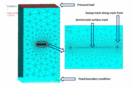
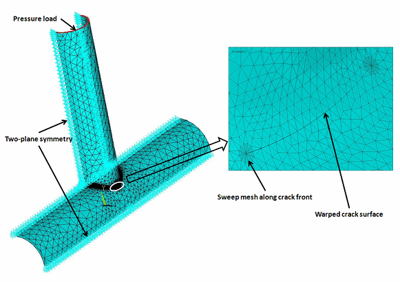
The rectangular block and x-joint pipe models are meshed with SOLID187 elements (except for the regions around the crack tip), as shown:
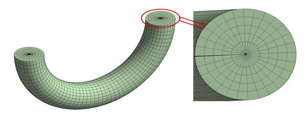
Regions around the crack tips are meshed with SOLID186, as shown:
Due to the two-plane symmetry of the x-Joint problem, a quarter model is considered for analysis, as shown:
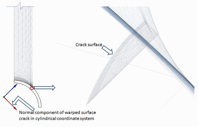
If the crack surface is not normal to any component in the global coordinate system, a local coordinate system should be created in such a way that one component of this coordinate system is perpendicular to the crack surface. For example, in the x-joint model, a local cylindrical coordinate system is created such that one of its components is normal to the crack surface, as shown:
In the x-joint model, the warped crack in the thickness direction is perpendicular to the inner surface of the 323.85 mm diameter pipe.
A torus is created around the crack front to obtain a good sweep mesh (VSWEEP). A common area separates the torus and the remaining volume at the interface.
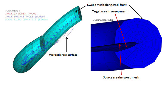
In 3D models, a fracture has two surfaces with a common edge at the crack front; the same is true for the torus. The two torus surfaces are used to create a clean sweep mesh around the crack front. One surface is defined as the source, the other as the target. In this procedure, the sweep mesh generates brick elements with one layer of prism elements around the crack front. Following is the sweep mesh with SOLID186 around the crack front in the x-joint pipe model, with the source and target areas for the sweep mesh indicated in the deformed body:
The warped surface contains a sweep mesh and a set of nodes, along with source and target areas in the deformed torus body. The source and target areas existed at the same location in the undeformed structure.
After meshing, crack parameters must be defined. The following example inputs show how to define parameters associated with contour integral calculation:
! Initiate a new contour integral calculation and define type
CINT, NEW, 1               ! Initiate new calculation and assign ID
CINT,TYPE,SIFS             ! Replace SIFS with JINT to find J-integral
! Define crack tip nodal component to find SIFs or J-integral for specified flaw
CINT,CTNC,component_name,,1
! Define symmetry details, number of contours to be calculated
CINT,SYMM,OFF              ! Symmetry off
CINT,NCON,6                ! Number of contours
! Define crack plane normal
CINT,NORMAL,0,2
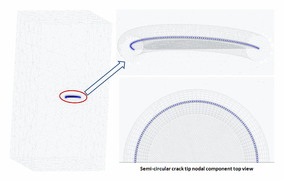
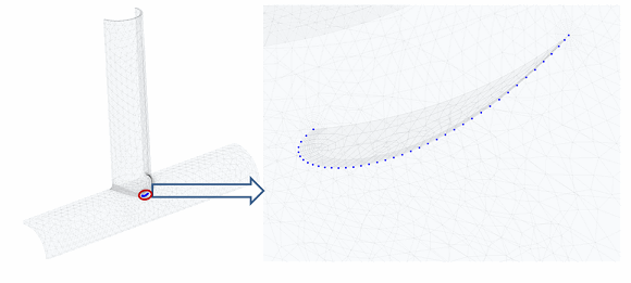
A line component of the crack front lines (CM) is created. This component is useful for selecting nodes attached to the crack front (NSLL). The nodal component of these nodes is used to define crack tip node components (CINT,CTNC), as shown in the following figures:


