Following is an examination of the results for each of the three impact scenarios:
Key option (KEYOPT) settings are those of the CONTA174 element.
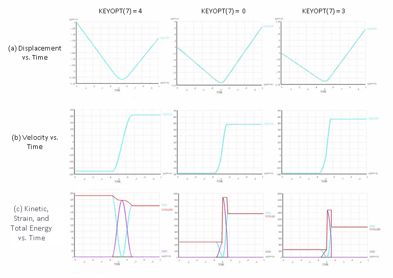
For rigid impact, the bar should hit the rigid wall and bounce back immediately with the same velocity. The total energy after the impact (SE+KE) should be same as the total energy before the impact (239.61 J).
As shown in the following table and subsequent figures, a comparison of the rebound velocity and the total energy at post-impact separation indicates that the rebound velocity is greater than the initial velocity when using either:
no control (KEYOPT(7) = 0), or
element-level time-incrementation control (based on contact-status changes (KEYOPT(7) = 3)) without numerical damping.
| CONTA174 Key Option Setting | NMK with No Damping | NMK with Damping | HHT with Damping | |||
| Rebound velocity (m/s) | Total energy after impact (J) | Rebound velocity (m/s) | Total energy after impact (J) | Rebound velocity (m/s) | Total energy after impact (J) | |
| KEYOPT(7) = 0 | 383.25 | 683.01 | 220.32 | 225.72 | 311.58 | 451.43 |
| KEYOPT(7) = 3 | 450.95 | 945.63 | 224.59 | 234.55 | 449.99 | 941.60 |
| KEYOPT(7) = 4 | 207.31 | 199.85 | 204.48 | 194.43 | 204.48 | 194.43 |
| KEYOPT(7) = 4 with Lagrange Multiplier | 227.00 | 239.61 | 227.00 | 239.61 | 227.00 | 239.61 |
The greater rebound velocity after impact is related to the absence of energy conservation, evidenced by the increase in the total energy. With impact constraints (KEYOPT(7) = 4), energy conservation is enforced, so there is no increase in the total energy or the rebound velocity.
Precise satisfaction of impact constraints is necessary to conserve energy and obtain the same rebound velocity as the initial velocity, as evidenced by a comparison of the results for impact constraints (KEYOPT(7) = 4) with augmented Lagrangian contact (KEYOPT(2) = 0), and Lagrange multiplier contact (KEYOPT(2) = 4).
Note: Lagrange multiplier contact for rigid bodies is generally not recommended due to the possibility of overconstraints. It is used here with CONTA175 at a single node (to avoid overconstraints) to demonstrate that energy conservation is dependent upon the exact satisfaction of impact constraints.
Figure 17.2: Rigid Impact: Newmark Method with No Damping
 |
|
Ranges for Y axis differ to better illustrate results. |
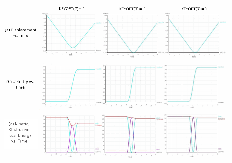
As shown in the following figure, adding numerical damping to the Newmark method helps to improve the results when using either:
No control (KEYOPT(7) = 0), or
Element-level time-incrementation control (based on contact-status changes (KEYOPT(7) = 3)).
Numerical damping removes some of the energy from the system and therefore counterbalances the increase in the total energy due to non-energy-conserving time integration, lowering the rebound velocity by a small amount.
Figure 17.3: Rigid Impact: Newmark Method with Damping
 |
|
Ranges for Y axis differ to better illustrate results. |
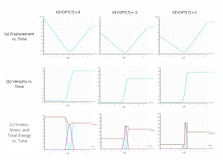
The HHT method removes energy only from the higher frequency modes (which are not dominant in the rigid-impact case). When compared to the Newmark method with damping, therefore, the HHT method does not yield as much improvement when KEYOPT(7) = 0 or 3, as shown in this figure:
Figure 17.4: Rigid Impact: HHT Method with Damping
 |
|
Ranges for Y axis differ to better illustrate results. |
Generally, impact constraints yield a close-to-expected or an expected solution, with or without damping. Other types of element-level time-incrementation controls (KEYOPT(7) = 0 or 3) rely heavily on numerical damping for a stable solution.
For elastic impact, the flexible bar begins to vibrate as the stress wave from impact with the rigid wall travels through the bar. When the stress wave returns to the impact end, the bar separates from the wall. Because the material is assumed to be elastic, the bar continues to vibrate as it moves away from the wall. Conservation of energy and momentum requires that the total energy in the bar after impact (SE+KE) remain equal to the total energy before impact (KE). Some of the initial kinetic energy (KE) is converted to strain energy (SE) after impact, so the rebound velocity after impact (spatially averaged velocity for rigid body motion) is slightly lower than the velocity before impact.
| CONTA174 Key Option Setting | NMK with No Damping | NMK with Damping | HHT with Damping | |||
| Rebound velocity (m/s) | Total energy after impact (J) | Rebound velocity (m/s) | Total energy after impact (J) | Rebound velocity (m/s) | Total energy after impact (J) | |
| KEYOPT(7) = 0 | 221.49 | 270.8 | 211.98 | 216.30 | 216.48 | 246.90 |
| KEYOPT(7) = 3 | 225.39 | 291.60 | 218.73 | 239.67 | 220.84 | 275.20 |
| KEYOPT(7) = 4 | 222.67 | 236.31 | 216.46 | 221.80 | 221.10 | 230.30 |
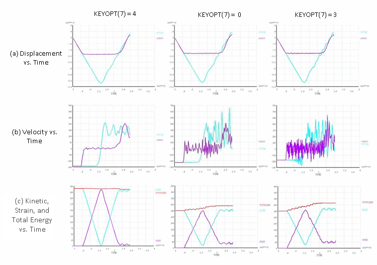
Finite-element discretization introduces additional nonphysical high-frequency modes into the structural response of the flexible bar. When using no control (KEYOPT(7) = 0) and no numerical damping, the displacement and velocity responses of the flexible bar become corrupted by high-frequency modes after impact, as shown in this figure:
Figure 17.5: Elastic Impact: Newmark Method with No Damping
 |
|
Ranges for Y axis differ to better illustrate results. |
The higher modes are excited due to absence of enforcement of energy conservation, as evidenced by the total energy output. The response becomes worse over time due to the continued increase in the total energy.
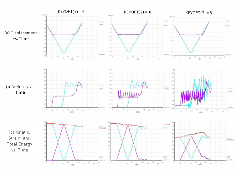
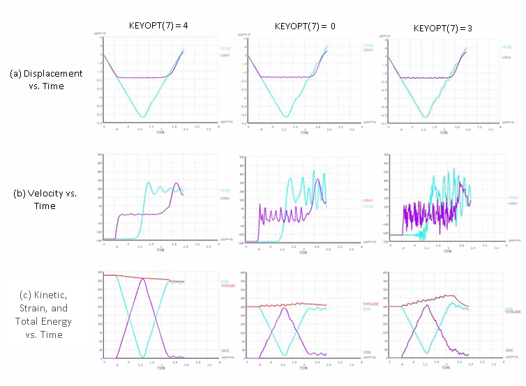
Adding numerical damping stabilizes the response by dissipating some of the extra energy, as shown in Figure 17.6: Elastic Impact: Newmark Method with Damping and Figure 17.7: Elastic Impact: HHT Method with Damping. Eliminating higher modes, however, requires a great deal of numerical damping, which can yield a solution that is significantly different from the expected physical response.
Figure 17.6: Elastic Impact: Newmark Method with Damping
 |
|
Ranges for Y axis differ to better illustrate results. |
Figure 17.7: Elastic Impact: HHT Method with Damping
 |
|
Ranges for Y axis differ to better illustrate results. |
Element-level time-incrementation control (based on contact-status changes (KEYOPT(7) = 3)) forces the analysis to use smaller time increments; however, this option leads to excitation of the higher modes which would otherwise be suppressed due to larger time increments. As seen from the results presented in this section, the solution is much noisier than it is with no control (KEYOPT(7) = 0).
Using impact constraints (KEYOPT(7) = 4) ensures energy conservation implicitly at the contact interface, preventing excitation of higher modes. Exact energy conservation is possible only when the impact constraints are satisfied exactly. When using the augmented Lagrangian or penalty-contact options (KEYOPT(2) = 0 or 1), a slight violation of constraints exists, leading to a small loss of energy. The energy loss is minimized via the program’s automatic time-increment adjustments; however, the adjustment decreases the rebound velocity after separation by only a small amount, giving a stable and smooth response much closer to the expected physical response and other published results for similar problems.[1]
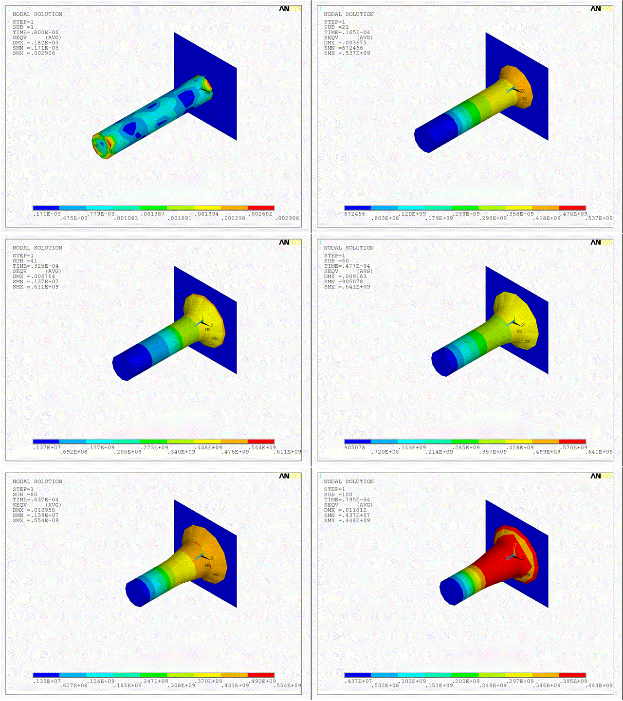
For elastoplastic impact, the impact end of the bar deforms plastically upon impact. The bar stays in contact with the wall while undergoing plastic deformation in radial and longitudinal directions. The separation occurs when the material cannot deform (plastically) anymore and the stress wave reaches the impact end.
Numerical simulation of an elastoplastic impact is less sensitive to the choice of time-integration method or the amount of numerical damping, as shown in this comparison of the mushroom radius (R), final length (L), maximum equivalent plastic strain (εpleqv), and maximum von Mises stress (σeqv):
| CONTA174 Key Option Setting | NMK with No Damping | NMK with Damping | HHT with Damping | |||||||||
| R | L | σ eqv | ε pl eqv | R | L | σ eqv | ε pl eqv | R | L | σ eqv | ε pl eqv | |
| KEYOPT(7) = 0 | 7.3 | 20.15 | 491.6 | 2.62 | 7.36 | 20.57 | 458.5 | 2.64 | 7.37 | 20.49 | 489.8 | 2.64 |
| KEYOPT(7) = 3 | 7.17 | 20.24 | 472.9 | 2.59 | 7.24 | 20.34 | 465.6 | 2.62 | 7.19 | 20.28 | 469.1 | 2.59 |
| KEYOPT(7) = 4 | 7.3 | 20.53 | 442.6 | 2.66 | 7.35 | 20.61 | 439.4 | 2.64 | 7.36 | 20.57 | 442.2 | 2.65 |
| Reference[2] | 7.02 | 21.66 | 476 | 3.24 | 7.02 | 21.66 | 476 | 3.24 | 7.02 | 21.66 | 476 | 3.24 |
In the table above, R and L are expressed in mm, and σeqv is expressed in MPa.
The numerical response is stable because the plastic dissipation of the total energy in the bar is much more significant than the jump in energy due to either non-conservation of energy during time integration or the dissipation of energy because of added numerical damping.
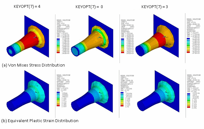
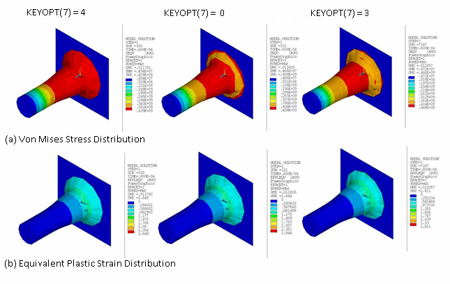
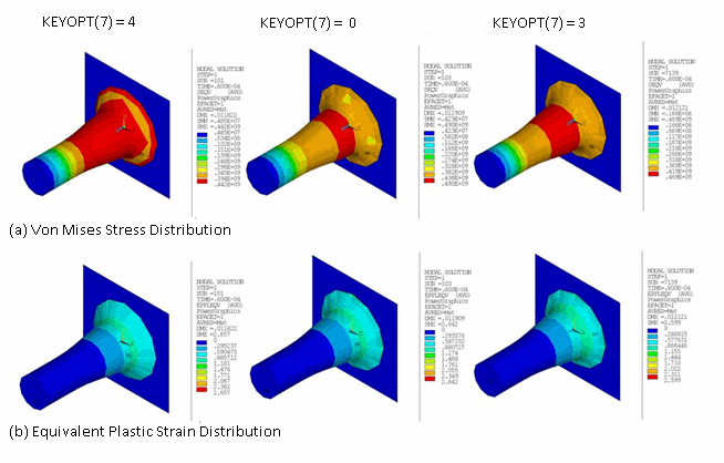
Although the peak values for stresses and strains are comparable for different choices, the contour plots for equivalent plastic strain and von Mises stress indicate that satisfaction of impact constraints (which conserves energy for the contact interface) gives a better distribution of the stresses and strains, as shown in the following figures:
Simulation time for the bar impact depends on the material model being used. The rigid-impact simulation requires the least amount of time, followed by the elastic-impact and then the elastoplastic-impact simulations. For each model, computational time (CPU time) depends most noticeably on the element-level time-incrementation controls used (KEYOPT(7) = 0, 3 or 4 on the CONTA174 element).
In the following table, a comparison of computational times (in seconds) indicates that using impact constraints with automatic time-increment adjustment (KEYOPT(7) = 4) requires the least amount of time in all cases:
| CONTA174 Key Option Setting | NMK with No Damping | NMK with Damping | HHT with Damping | |||
| Rigid Impact | ||||||
| KEYOPT(7) = 0 | 39 | 42 | 45 | |||
| KEYOPT(7) = 3 | 179 | 321 | 190 | |||
| KEYOPT(7) = 4 | 45 | 41 | 44 | |||
| KEYOPT(7) = 4 with Lagrange Multiplier | 38 | 41 | 41 | |||
| Elastic Impact | ||||||
| KEYOPT(7) = 0 | 783 | 638 | 753 | |||
| KEYOPT(7) = 3 | 12186 | 11511 | 13091 | |||
| KEYOPT(7) = 4 | 404 | 413 | 507 | |||
| Elastoplastic Impact | ||||||
| KEYOPT(7) = 0 | 976 | 697 | 834 | |||
| KEYOPT(7) = 3 | 24048 | 23330 | 25976 | |||
| KEYOPT(7) = 4 | 591 | 556 | 621 | |||
By using impact constraints with automatic time-increment adjustment, fewer substeps and equilibrium iterations are necessary to obtain the transient response.
With no control (KEYOPT(7) = 0), more analysis time is required, as more substeps and equilibrium iterations are required. The absence of energy conservation at the contact interface forces smaller time increments.
Using element-level time-incrementation control based on contact status changes (KEYOPT(7) = 3) requires the most time, as smaller time increments are necessary to avoid sudden changes in the contact status.


