


Analysis of the flip chip is performed via a 1/8 symmetry model. A symmetric boundary condition is applied to two cut planes in both the thermal and the structural analyses.
The following related topics are available:
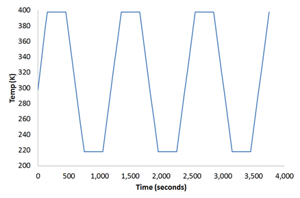
An initial temperature of 298 K is applied on all nodes.
The temperature on the free surface of the chip is increased at a constant rate for 150 seconds to 398 K.
The same constant temperature is maintained in the next load step for 300 seconds, then cooled to 218 K in 300 seconds.
The following figure illustrates each heating phase and each cooling phase, and the constant temperature maintained for 300 seconds between each phase:
The following input defines the initial temperature:
NSEL,ALL						! Select all nodes
IC,ALL,TEMP,298			! Specifies initial temperature at nodes
Temperature degree-of-freedom constraints are used to apply loading on the chip surface, as shown in the following input:
NSEL,S,LOC,Y,1.325		! Select free surface nodes of chip
D,ALL,TEMP,218			! Applied temperature
ALLSEL,ALL
The temperature profile at different time steps (obtained from a transient thermal analysis) is used in nonlinear structural analysis to predict residual creep strains in solder. The following command reads thermal analysis temperature results as thermal loads at different time steps:
LDREAD,TEMP,,,TIME,0,'thermal','rth' ! Read temperature from thermal analysis results fileIssue the LDREAD command at every substep to read the
temperature at the appropriate time. Change the TIME
value to the final solution time of a given substep. A linear variation in the
solder temperature between load steps is observed; therefore, the thermal load is
applied at the end of each load step rather than to each substep.
Rigid body motion is constrained with displacement of all degrees of freedom at the center of a substrate bottom node.