The following boundary and loading condition data is available for this problem:
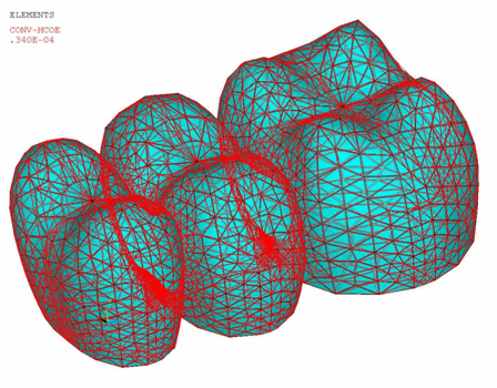
An initial temperature of 700° C is applied on all nodes. A convective heat-transfer coefficient of 3.4E-5 W/mm2 °C is specified on all free surfaces of the FPD.
The following example input defines the initial temperature and convection coefficient:
NSEL,ALL                   ! Select all nodes
IC,ALL,TEMP,700            ! Specifies initial temperature at nodes

!        Apply convection on the outer areas of the FPD

CMSEL,S,VOAN,NODE          ! Select veneer outer area nodes
CMSEL,A,BAN,NODE           ! Select FPD bottom area nodes
SF,ALL,CONV,3.4E-5,30      ! Convection
The following figure shows the model with the initial temperature and convection on the FPD surface applied:
For the contact pair, a thermal contact conductance of 4E-05 J/(sec-°C) is used for heat conduction between the veneer and the core.
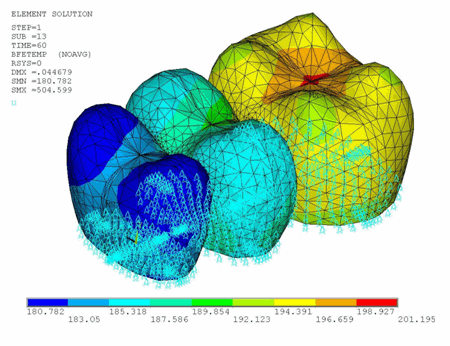
Rigid body motion is constrained with appropriate displacement constraints at the midline of the FPD base. Vertical displacement constraints are applied to all base nodes. The thermal load is applied (LDREAD).
The following example input reads the temperature from the thermal analysis results:
LDREAD,TEMP,,,TIME,0,'thermal','rth' ! Read temperature from thermal analysis results fileThe temperature is read at every load step (LDREAD). The
TIME value represents the final solution time of each
load step.
The following figure shows the displacement boundary conditions and body force at TIME = 60 seconds.


