


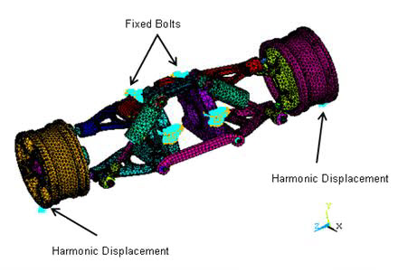
As shown in the following figure, the six bolts on top of the body are constrained in all directions. Sinusoidal displacement excitation is applied at three nodes at the bottoms of both wheels.
The following example input shows how the boundary conditions are applied in the generation pass of the CMS model:
/FILNAME, BODY
/SOLU
/COM,  SELECT A SUBSET OF THESE NODES
CMSEL, S, BOLT1   		! Select a new subset of components named Bolt1
CMSEL, A, BOLT2   		! Additionally select a set Bolt2 and extend the current set
CMSEL, A, BOLT3   		! Additionally select a set Bolt3 and extend the current set
CMSEL, A, BOLT4   		! Additionally select a set Bolt4 and extend the current set
CMSEL, A, BOLT5   		! Additionally select a set Bolt5 and extend the current set
CMSEL, A, BOLT6   		! Additionally select a set Bolt6 and extend the current set
ESLN							! Select the elements attached to the selected nodes
NSLE							! Select the nodes attached to the selected elements
D, ALL, ALL   			! Constrain the nodes for all degrees of freedom
The loading is applied in the form of harmonic displacement in the vertical y direction on a selected set of nodes on boththe wheels. The sample input shows how the displacement loading is applied in the full harmonic analysis:
/COM, NODES AT THE BOTTOM OF THE FIRST WHEEL FOR EXCITATION
N1=NODE(-0.13838, -0.28280, 1.0714)	! Node #191882
N2=NODE(-0.13733, -0.28293, 1.0501)	! Node #192365
N3=NODE(-0.13786, -0.28287, 1.0608)	! Node #210243

/COM, NODES AT THE BOTTOM OF THE SECOND WHEEL FOR EXCITATION
N4=NODE(-0.14007, -0.28151, -1.3531)	! Node #260357
N5=NODE(-0.14043, -0.28140, -1.3638)	! Node #278577
N6=NODE(-0.14079, -0.28129, -1.3744)	! Node #259968
FINISH

/SOLU
ANTYPE, HARMONIC			! Perform a harmonic analysis
HROPT, FULL	          ! Employ the full method
KBC, 1	               ! Use the same value of the load for each substeps
DMPRAT, 0.05				! Set a damping ratio of 5%

HARFRQ, 160, 200 		! Choose the frequency range between 160 and 200 Hz
NSUBST, 20					! Number of substeps = 20

/COM, LOCATION OF THE LOAD ON THE FIRST WHEEL

NSEL, S, NODE, , N1	! Select the node n1 as a new subset
NSEL, A, NODE, , N2	! Additionally select the node n2 and extend the current set
NSEL, A, NODE, , N3	! Additionally select the node n3 and extend the current set

/COM, LOCATION OF THE LOAD ON THE SECOND WHEEL

NSEL, A, NODE, , N4	! Additionally select the node n4 and extend the current set
NSEL, A, NODE, , N5	! Additionally select the node n5 and extend the current set
NSEL, A, NODE, , N6	! Additionally select the node n6 and extend the current set

D, ALL, UY, 100			! Define a displacement degree of freedom on these nodes in the y
									! direction. This harmonic displacement amplitude = 100.
NSEL, ALL					! Restore the full set of nodes before solving
SOLVE 							! Solve the full model for harmonic analysis
FINISH