The example consists of an eight stage centrifugal compressor supported by two tilting pad bearings. It is modeled with beam (BEAM188), bearing elements (COMBI214), and points masses (MASS21). APDLMath commands are used to directly calculate the critical speeds and generate the critical speed map.
/filename,tutor-rag07s

/prep7
! *** material
mp, ex, 1, 1.33414e+11
mp, dens, 1, 7833.3834
mp, prxy, 1, 0.3

! *** rotor geometry
et, 1, beam188,,, 2
nbdiam = 34
*dim, diam, array, nbdiam
diam(1)  = 0.06985
diam(2)  = 0.110744
diam(3)  = 0.127
diam(4)  = diam(3)
diam(5)  = 0.1651
diam(6)  = 0.168148
diam(7)  = 0.157988
diam(8)  = 0.182372
diam(9)  = 0.17018
diam(10) = diam(9)
diam(11) = diam(9)
diam(12) = diam(9)
diam(13) = diam(9)
diam(14) = diam(9)
diam(15) = diam(9)
diam(16) = diam(9)
diam(17) = diam(9)
diam(18) = diam(9)
diam(19) = diam(9)
diam(20) = diam(9)
diam(21) = diam(9)
diam(22) = diam(9)
diam(23) = diam(9)
diam(24) = diam(9)
diam(25) = diam(9)
diam(26) = 0.1778
diam(27) = 0.168148
diam(28) = diam(27)
diam(29) = 0.1651
diam(30) = 0.127
diam(31) = diam(30)
diam(32) = 0.118872
diam(33) = 0.094996
diam(34) = 0.093472
*do,i,1,nbdiam
   sectype, i, beam, csolid
   secdata, diam(i)/2
*enddo

! *** point masses
et, 2, mass21
r,101,72.1224,72.1224,72.1224
r,102,3.22056,3.22056,3.22056
r,103,4.58136,4.58136,4.58136
r,104,2.54016,2.54016,2.54016
r,105,4.39992,4.39992,4.39992
r,106,5.57928,5.57928,5.57928
r,107,5.67,5.67,5.67
r,108,7.4844,7.4844,7.4844
r,109,6.66792,6.66792,6.66792
r,110,33.3396,33.3396,33.3396,0.1805617,0.09042717,0.09042717       ! disk
r,111,7.80192,7.80192,7.80192,0.00992065,0.00520907,0.00520907
r,112,33.3396,33.3396,33.3396,0.1805617,0.09042717,0.09042717       ! disk
r,113,7.80192,7.80192,7.80192,0.00992065,0.00520907,0.00520907
r,114,33.3396,33.3396,33.3396,0.1805617,0.09042717,0.09042717       ! disk
r,115,7.80192,7.80192,7.80192,0.00992065,0.00520907,0.00520907
r,116,36.69624,36.69624,36.69624,0.1805617,0.09042717,0.09042717    ! disk
r,117,13.19976,13.19976,13.19976
r,118,36.92304,36.92304,36.92304,0.1805617,0.09042717,0.09042717    ! disk
r,119,9.5256,9.5256,9.5256,0.01436885,0.00793067,0.00793067
r,120,34.33752,34.33752,34.33752,0.1805617,0.09042717,0.09042717    ! disk
r,121,9.5256,9.5256,9.5256,0.01436885,0.0079014,0.0079014
r,122,34.33752,34.33752,34.33752,0.1805617,0.09042717,0.09042717    ! disk
r,123,9.5256,9.5256,9.5256,0.01436885,0.00793067,0.00793067
r,124,36.56016,36.56016,36.56016,0.1805617,0.09042717,0.09042717    ! disk
r,125,17.14608,17.14608,17.14608,0.04799371,0.03540999,0.03540999
r,126,5.62464,5.62464,5.62464
r,127,5.94216,5.94216,5.94216
r,128,5.71536,5.71536,5.71536
r,129,5.53392,5.53392,5.53392
r,130,4.39992,4.39992,4.39992
r,131,1.99584,1.99584,1.99584
r,132,3.58344,3.58344,3.58344
r,133,7.39368,7.39368,7.39368
r,134,9.43488,9.43488,9.43488
r,135,4.71744,4.71744,4.71744

! *** bearing (YZ plane)
et, 3, 214
keyopt, 3, 2, 1
keyopt, 3, 3, 0

*dim, kb, array, 10, 1, 1
kb(1,1) = 1751181.1, 3772744.57, 8128282.20, 17511811.02, 37717971.02, 81282646.93, 175118110.24, 377280585.83, 812826294.17, 1751181102.36

r,3, kb(1,1), kb(1,1)

! *** nodes (shaft along X)
n, 1 , 0.
n, 2 , 0.034544
n, 3 , 0.20574
n, 4 , 0.24384
n, 5 , 0.287274
n, 6 , 0.375412
n, 7 , 0.429768
n, 8 , 0.51943
n, 9 , 0.60579
n, 10, 0.668274
n, 11, 0.747014
n, 12, 0.809498
n, 13, 0.888238
n, 14, 0.950722
n, 15, 1.029462
n, 16, 1.091946
n, 17, 1.251966
n, 18, 1.411986
n, 19, 1.484122
n, 20, 1.575054
n, 21, 1.64719
n, 22, 1.738122
n, 23, 1.810258
n, 24, 1.90119
n, 25, 2.028444
n, 26, 2.10185
n, 27, 2.160524
n, 28, 2.250694
n, 29, 2.30505
n, 30, 2.39268
n, 31, 2.436114
n, 32, 2.474214
n, 33, 2.61874
n, 34, 2.666238
n, 35, 2.806192
n, 40 , 0.24384
n, 310, 2.436114

! *** mesh
type, 1
mat, 1
*do,i,1,nbdiam
   secnum, i
   e, i, i+1
*enddo
type, 2
*do,i,1,nbdiam+1
   real, i+100
   e, i
*enddo
type, 3
real, 3
e, 4, 40
e, 31, 310

! *** boundary conditions
d, all, ux ,,,,,rotx
d, 40,  all
d, 310, all
fini

! *** Example of how to determine critical speeds
!     -------------------------------------------
! ** modify the bearing stiffness
/prep7
rmodif, 3, 1, kb(5,1), kb(5,1)
finish

! ** write the full file
/solu
antype, modal
modopt, damp, 2
coriolis, on,,, on
omega, 1.0			! unit rotational velocity to get [G1]
wrfull, 1	      		! stop solve when the full file is written
solve
fini

! ** read matrices on the full file
*smat, K , D,IMPORT,FULL,tutor-rag07s.full, STIFF
*smat, M , D,IMPORT,FULL,tutor-rag07s.full, MASS
*smat, G1, D,IMPORT,FULL,tutor-rag07s.full, DAMP

! ** obtain the new eigenproblem matrices
alpha = 1.0
*smat, zMbar, Z, COPY, M
*axpy,, -1/alpha, G1, 1,, zMbar
*smat, zK, Z, COPY, K
*free,K
*free,M
*free,G1

! ** solve the new eigenproblem

/solu
antype, modal
modopt, unsym , 10
*eigen, zK, zMbar,, eigenVal, eigenVec
fini
*free,zK
*free,eigenVec

! ** store the critical speeds
*dim, critspeed1, ARRAY, 5
_coefunit = 60/alpha                         ! Hz -> rpm
*do,_iloop,1,5
   xx = eigenVal(_iloop*2,1)*_coefunit       ! real part of the eigenvalue (FW)
   critspeed1(_iloop) = xx
*enddo
*free,eigenVal
*status,critspeed1

! ** Obtain the complete critical speed map
!    Macro CRITSPEEDMAP.MAC
!       ARG1      Number of critical speeds
!       ARG2      Number of excitations per revolution
!                         =0  Defaults to 1.0 (synchronous excitation)
!       Bearings stiffness
!       ARG3      Lowest value
!       ARG4      Highest value
!       ARG5      Number of steps
!                         =0  Defaults to 10
!       Rotational velocity direction (normalized to unity)
!       ARG6      X component
!       ARG7      Y component
!       ARG8      Z component
!
!       Eigensolver parameter
!       ARG9      Beginning of the frequency range (defaults to 1 Hz)
!--------------------------------------------
/show,JPEG
critspeedmap, 5,, kb(1,1), kb(10,1),, 1,0,0
/show,CLOSE
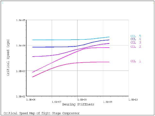
The critical speed map is shown in Figure 7.11: Critical Speed Map.