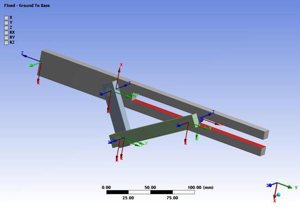
Define the joints that connect the parts of the crank slot model. Revolute, slot, and cylindrical joints form the moving joints. The base of the model is fixed to the ground via a fixed joint.
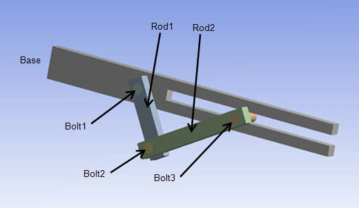
The following figure shows the parts of the model, with the joints listed to the right:
 |
|
All joints are available via the MPC184 element's KEYOPT(1) setting and, in some cases, the KEYOPT(4) setting. For more information, see Connecting Multibody Components with Joint Elements.