This example demonstrates the use of stage clones, each of which is associated with a particular harmonic index, to perform a multiharmonic modal analysis of a simplified hollow cylinder modeled using two stages. Specifically, it demonstrates the following key points:
Creating a stage clone
Axial multistage modeling
Matched interstage boundaries
Applying interstage constraints to fully connect stages
Connecting all primary stages and stage clones together
The example problem is presented in the following sections:
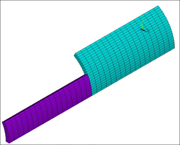
The multistage system consists of two axially aligned cyclic stages of a hollow cylinder merged at a matched interstage boundary (Figure 7.21: Multistage Model of a Hollow Cylinder). Each stage is a sector of a hollow cylinder with different sector sizes. Stage 1 has 6 sectors while stage 2 has 12 sectors. While it is not possible to see, the model for stage 2 has two identical meshes, one for the primary stage and one for the stage clone. The interstage boundary conditions are applied in two separate steps. The first step applies interstage constraints for the primary stages (HI = 0 in this case), and the second step applies interstage constraints for the primary stage for stage 1 (HI = 0) and the stage clone for stage 2 (HI = 6). The modal analysis is run, and then a full 360° case is run to compare the modal frequencies.
Note: Multistage expansion is not currently supported for multiharmonic analyses.
The following table describes the key steps and related commands used for the example analysis. See Input for the Analysis for the detailed command listing.
| Step | Description | Mechanical APDL Commands |
| 1. | Create meshes |
CYLIND,... VMESH,... |
| 2. | Write .cbd files for each stage. | CDWRITE,... |
| 3. | Read in stage clones and primary stages. | CDREAD,... |
| 4. | Create stage components. | CM,... |
| 5. | Create stage and stage clones. | MSOPT,NEW,... |
| 6. | Apply boundary conditions. | D,... |
| 7. | Select interface nodes and elements for primary stages. | CMSEL,... |
| 8. | Apply interstage constraints for primary stages. | CEIMS,... |
| 9. | Select interface nodes and elements for stage clone for secondary harmonic and primary stage for primary harmonic. | CMSEL,... |
| 10. | Apply interstage constraints for stage clone for secondary harmonic and primary stage for primary harmonic. | CEIMS,... |
| 11. | Enter solution processor | /SOLU |
| 12. | Specify modal options | MODOPT,... |
| 13. | Solve the analysis | SOLVE |
| 14. | Enter/POST1 processor | /POST1 |
| 15. | List modal frequencies | SET,LIST |
Download the zipped .cdb files used for this example problem.
/batch
/com ===============================================================
/com    Multistage multiharmonic modal analysis - hollow cylinder
/com ===============================================================

!create sector mesh for stage1
!-------------------------------
/prep7

nu = 0.3
rho = 7800
e = 2e+11

ET,1,SOLID186
MP,EX,1,E
MP,DENS,1,RHO
MP,NUXY,1,NU
TYPE,1
MAT,1

ro = 0.2
ri = 0.18
ltot = 1
elsz = 0.01
mratio = 3     !ratio between element size along thickness / along length
theta1 = 60
nsect1 = 360/theta1

CYLIND, RI,RO, 0,ltot/2, 0,theta1

! mesh
!---------
NUMMRG,KP
ESIZE,ELSZ
LSEL,,LOC,Z,ltot/4
LESIZ,ALL,elsz*mratio
LSEL,,LOC,Z,0
LSEL,A,LOC,Z,ltot/2
CSYS,1
LSEL,R,LOC,Y,theta1/2
LESIZ,ALL,,,20
ALLSEL
CSYS,0
VMESH,ALL

! write stage1 sector to file
!------------------------------------
cdwrite,db,sect1,cdb
parsav,,sect,parm
finish

/clear, nostart

! create sector mesh for stage2
!-----------------------------------------
/prep7
parres,,sect,parm

ET,1,SOLID186
MP,EX,1,E
MP,DENS,1,RHO
MP,NUXY,1,NU

TYPE,1
MAT,1

theta2 = 30
nsect2 = 360/theta2

CYLIND, RI,RO, ltot/2,ltot, 0,theta2

! mesh
!---------
NUMMRG,KP
ESIZE,elsz
LSEL,,LOC,Z,3*ltot/4
LESIZ,ALL,elsz*mratio
LSEL,,LOC,Z,ltot/2
LSEL,A,LOC,Z,ltot
CSYS,1
LSEL,R,LOC,Y,theta2/2
LESIZ,ALL,,,10
ALLSEL
CSYS,0
VMESH,ALL

! write stage 2 sector to file
!-------------------------------------
cdwrite,db,sect2,cdb
parsav,,sect,parm
finish

/clear, nostart

/com ===============================================================
/com    Multistage simulation - hollow cylinder
/com ===============================================================

parres,,sect,parm

cdread,db,sect2,cdb    ! stage2 HI6 (stage clone)
cdread,db,sect2,cdb    ! stage2 HI0
cdread,db,sect1,cdb    ! stage1 HI0

HI1 = 0
HI2A = 0
HI2B = 6

/prep7
csys,1

!--------------------------------------------------
! Prepare stage1
!--------------------------------------------------

! create components for stage1, HI = 0
!--------------------------------------
esel,,type,,1
cm, _STAGE1_BASE_ELM, ELEM
nsle
cm, _STAGE1_BASE_NOD, NODE
allsel
ESEL,,TYPE,,1
NSLE
NSEL,R,LOC,Y,0
CM,_STAGE1_CYCLOW_NOD,NODE
ESEL,,TYPE,,1
NSLE
NSEL,R,LOC,Y,theta1
CM,_STAGE1_CYCHIGH_NOD,NODE
ALLSEL

! create stage1 and cyclic CEs
!----------------------------------------
msopt,new,stage1,NSECT1,HI1
CECYCMS

!--------------------------------------------------
! Prepare stage2A, HI = 0
!--------------------------------------------------

! create components for stage2A, HI = 0
!-----------------------------------------------------
esel,,type,,2
cm,_STAGE2A_BASE_ELM,ELEM
nsle
cm,_STAGE2A_BASE_NOD,NODE
allsel
ESEL,,TYPE,,2
NSLE
NSEL,R,LOC,Y,0
CM,_STAGE2A_CYCLOW_NOD,NODE
ESEL,,TYPE,,2
NSLE
NSEL,R,LOC,Y,theta2
CM,_STAGE2A_CYCHIGH_NOD,NODE
ALLSEL

! create stage2A and cyclic CEs, HI = 0
!--------------------------------------------------
msopt,new,stage2A,NSECT2,HI2A
CECYCMS

!--------------------------------------------------
! Prepare stage2B, HI = 6
!--------------------------------------------------

! create components for stage2B
!-------------------------------------------
esel,,type,,3
cm, _STAGE2B_BASE_ELM, ELEM
nsle
cm, _STAGE2B_BASE_NOD, NODE
allsel
ESEL,,TYPE,,3
NSLE
NSEL,R,LOC,Y,0
CM,_STAGE2B_CYCLOW_NOD,NODE
ESEL,,TYPE,,3
NSLE
NSEL,R,LOC,Y,theta2
CM,_STAGE2B_CYCHIGH_NOD,NODE
ALLSEL

! create stage2B and cyclic CEs, HI = 6
!--------------------------------------
msopt,new,stage2B,NSECT2,HI2B,,,,,stage2A
CECYCMS

! Apply boundary conditions
!--------------------------------------
nsel,,loc,Z,0
nsel,a,loc,Z,ltot
d,all,all
allsel

! Select interstage nodes and elements for stage1 and stage2A
!----------------------------------------------------------------------------------
ESEL,,TYPE,,1
NSLE
NSEL,R,LOC,Z,ltot/2
CM,CM_INTF1_NODE,NODE
NSEL,,LOC,Z,ltot/2
ESLN
ESEL,R,TYPE,,2
CM,CM_INTF2_1_ELEM,ELEM
ALLSEL
CMSEL,,CM_INTF1_NODE
CMSEL,,CM_INTF2_1_ELEM
! Apply interstage CEs - stage1, HI0 <=> stage2A, HI0
!----------------------------------------------------------------------
CEIMS,,,stage1,stage2A
msopt,list,all,1
ALLSEL

! Select interstage nodes and elements for stage1 and stage2B
!-----------------------------------------------------------------------
NSEL,,LOC,Z,ltot/2
ESLN
ESEL,R,TYPE,,3
CM,CM_INTF2_2_ELEM,ELEM
ALLSEL
CMSEL,,CM_INTF1_NODE
CMSEL,,CM_INTF2_2_ELEM
! Apply interstage CEs - stage1, HI0 <=> stage2B, HI6
!-----------------------------------------------------------------------
CEIMS,,,stage1,stage2B
msopt,list,all,1
ALLSEL
fini

/solu
antype,modal
modopt,lanb,3,0,3150
solve
finish

/post1
/com =======================================
/com  Multistage modal frequencies
/com =======================================
set,list
/com =======================================
finish

/clear,nostart
/com ===============================================================
/com    Full 360 degree reference simulation - hollow cylinder
/com ===============================================================

parres,,sect,parm

cdread,db,sect2,cdb    ! stage 2
cdread,db,sect1,cdb    ! stage 1

*get,nnode,node,,num,max

/prep7

csys,1

! form 360 stage 1
!--------------------
nsel,s,loc,z,0,ltot/2
esln,,1
egen,nsect1,nnode,all,,,,,,,,0,theta1,0
allsel
esel,,type,,1
nsle
nummrg,node
esel,,type,,1
nsle
nsel,r,loc,z,ltot/2
cm,stage1_node_intf,node
allsel

! form 360 stage 2
!-------------------
nsel,s,loc,z,ltot/2,ltot
esln,,1
egen,nsect2,nnode,all,,,,,,,,0,theta2,0
allsel
esel,,type,,2
nsle
nummrg,node
allsel
nsel,,loc,z,ltot/2
esln
esel,r,type,,2
cm,stage2_elem_intf,elem
allsel

! tie stages
cmsel,,stage1_node_intf
cmsel,,stage2_elem_intf
ceintf,,all
allsel

! BC
nsel,,loc,Z,0
nsel,a,loc,Z,ltot
d,all,all
allsel
finish

/solu
antype,modal
modopt,lanb,37,0,3150
solve
finish

/post1
/com =======================================
/com  Full 360 reference modal frequencies
/com =======================================
set,list
/com =======================================
set,1,11
/show,png,rev
/view,1,1,1,1
plnsol,u,sum
set,1,26
plnsol,u,sum
set,1,37
plnsol,u,sum
/show,close
finish
To list multistage cyclic symmetry settings and stage connections in the output, use the MSOPT,LIST command. The listing for this example is shown below.
MULTISTAGE OPTION: LIST STAGES DETAILED INFORMATION
    TOTAL NUMBER OF STAGES =     3
    COORDINATE SYSTEM      =     1 (DEFAULT)
    CURRENT STAGE FOR APPLYING CYCLIC CONSTRAINTS =   STAGE2B

     --------------------  STAGE =   STAGE1  --------------------
          NUMBER OF SECTORS =     6
          HARMONIC INDEX    =     0
          NO DUPLICATE SECTOR

          TOTAL NUMBER OF NODES    =      4041
          TOTAL NUMBER OF ELEMENTS =       680

          BOUNDING BOX OF STAGE NODES
              RADIAL DIRECTION MIN,MAX     =  0.1800E+00  0.2000E+00
              TANGENTIAL DIRECTION MIN,MAX =      0.00     60.00     (deg)
              AXIAL DIRECTION MIN,MAX      =  0.0000E+00  0.5000E+00

          CYCLIC CONSTRAINT EQUATIONS
             TOTAL NUMBER (ACTIVE)    =     408
             NUMBER OF FIRST EQUATION =       1
             NUMBER OF LAST EQUATION  =     423

          STAGE IS CONNECTED WITH STAGE = STAGE2A
               MULTISTAGE INTERFACE CONSTRAINT EQUATIONS
                  TOTAL NUMBER (ACTIVE)    =     495
                  NUMBER OF FIRST EQUATION =    1270
                  NUMBER OF LAST EQUATION  =    1764

          STAGE IS CONNECTED WITH STAGE = STAGE2B

     --------------------  STAGE =   STAGE2A  --------------------
          NUMBER OF SECTORS =    12
          HARMONIC INDEX    =     0
          NO DUPLICATE SECTOR

          TOTAL NUMBER OF NODES    =      2091
          TOTAL NUMBER OF ELEMENTS =       340

          BOUNDING BOX OF STAGE NODES
              RADIAL DIRECTION MIN,MAX     =  0.1800E+00  0.2000E+00
              TANGENTIAL DIRECTION MIN,MAX =      0.00     30.00     (deg)
              AXIAL DIRECTION MIN,MAX      =  0.5000E+00  0.1000E+01

          CYCLIC CONSTRAINT EQUATIONS
             TOTAL NUMBER (ACTIVE)    =     423
             NUMBER OF FIRST EQUATION =     424
             NUMBER OF LAST EQUATION  =     846

          STAGE IS CONNECTED WITH STAGE = STAGE1

          STAGE IS THE FIRST HARMONIC OF STAGE = STAGE2B

     --------------------  STAGE =   STAGE2B  --------------------
          NUMBER OF SECTORS =    12
          HARMONIC INDEX    =     6
          NO DUPLICATE SECTOR

          TOTAL NUMBER OF NODES    =      2091
          TOTAL NUMBER OF ELEMENTS =       340

          BOUNDING BOX OF STAGE NODES
              RADIAL DIRECTION MIN,MAX     =  0.1800E+00  0.2000E+00
              TANGENTIAL DIRECTION MIN,MAX =      0.00     30.00     (deg)
              AXIAL DIRECTION MIN,MAX      =  0.5000E+00  0.1000E+01

          CYCLIC CONSTRAINT EQUATIONS
             TOTAL NUMBER (ACTIVE)    =     423
             NUMBER OF FIRST EQUATION =     847
             NUMBER OF LAST EQUATION  =    1269

          STAGE IS CONNECTED WITH STAGE = STAGE1

          STAGE IS A HARMONIC OF STAGE = STAGE2A
     ---------------------------------------------------------------------------
The input generates modal frequencies for the multistage analysis for the primary harmonic index 0 listed in Table 7.1: Multistage Modal Frequencies. These frequencies can be compared to the full 360° frequencies shown in Table 7.2: Full Model Modal Frequencies. Since the full 360° analysis generates results for the entire harmonic index spectrum, the values to compare are highlighted. The values from the multistage analysis and the full analysis match well.
Table 7.1: Multistage Modal Frequencies
| SET | TIME/FREQ | LOAD STEP | SUBSTEP | CUMULATIVE |
|---|---|---|---|---|
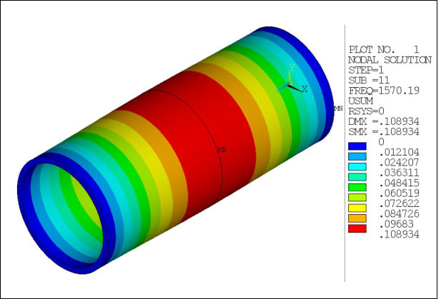
| 1 | 1570.2 | 1 | 1 | 1 |
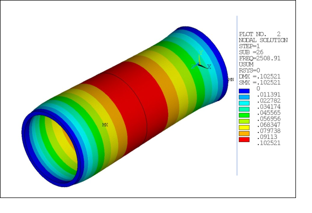
| 2 | 2508.9 | 1 | 2 | 2 |
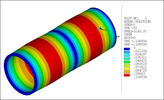
| 3 | 3140.4 | 1 | 3 | 3 |
Table 7.2: Full Model Modal Frequencies
| SET | TIME/FREQ | LOAD STEP | SUBSTEP | CUMULATIVE |
|---|---|---|---|---|
| 1 | 672.35 | 1 | 1 | 1 |
| 2 | 672.35 | 1 | 2 | 2 |
| 3 | 1020.2 | 1 | 3 | 3 |
| 4 | 1020.2 | 1 | 4 | 4 |
| 5 | 1100.2 | 1 | 5 | 5 |
| 6 | 1100.2 | 1 | 6 | 6 |
| 7 | 1275.5 | 1 | 7 | 7 |
| 8 | 1275.5 | 1 | 8 | 8 |
| 9 | 1394.1 | 1 | 9 | 9 |
| 10 | 1394.1 | 1 | 10 | 10 |
| 11 |
1570.2 | 1 | 11 | 11 |
| 12 | 1868.5 | 1 | 12 | 12 |
| 13 | 1868.5 | 1 | 13 | 13 |
| 14 | 1969.0 | 1 | 14 | 14 |
| 15 | 1969.0 | 1 | 15 | 15 |
| 16 | 1980.5 | 1 | 16 | 16 |
| 17 | 1980.5 | 1 | 17 | 17 |
| 18 | 1984.3 | 1 | 18 | 18 |
| 19 | 1984.3 | 1 | 19 | 19 |
| 20 | 2150.5 | 1 | 20 | 20 |
| 21 | 2150.5 | 1 | 21 | 21 |
| 22 | 2445.8 | 1 | 22 | 22 |
| 23 | 2445.8 | 1 | 23 | 23 |
| 24 | 2471.2 | 1 | 24 | 24 |
| 25 | 2471.2 | 1 | 25 | 25 |
| 26 |
2508.9 | 1 | 26 | 26 |
| 27 | 2662.6 | 1 | 27 | 27 |
| 28 | 2662.6 | 1 | 28 | 28 |
| 29 | 2905.1 | 1 | 29 | 29 |
| 30 | 2905.1 | 1 | 30 | 30 |
| 31 | 2918.5 | 1 | 31 | 31 |
| 32 | 2918.5 | 1 | 32 | 32 |
| 33 | 3071.7 | 1 | 33 | 33 |
| 34 | 3071.7 | 1 | 34 | 34 |
| 35 | 3093.2 | 1 | 35 | 35 |
| 36 | 3093.2 | 1 | 36 | 36 |
| 37 |
3140.4 | 1 | 37 | 37 |
The contour plots for the full 360° results are presented in Figure 7.22: Fundamental Harmonic Index 0 Response at 1570.2 Hz, Figure 7.23: Fundamental Harmonic Index 0 Response at 2508.9 Hz, and Figure 7.24: Fundamental Harmonic Index 0 Response at 3140.4 Hz. The plots show that the response is truly a harmonic index 0 response, that is, all sectors have the same response. It is noted that in the multistage response, the inclusion of harmonic index 6 for stage 2 is necessary to get the correct response of the system.