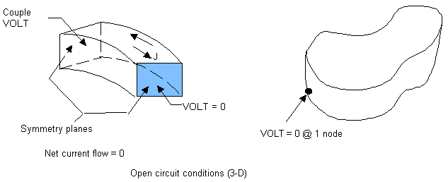
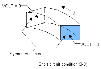
Mechanical APDL offers several options you can use to handle terminal conditions on conductors in 3D magnetic analyses. Figure 6.1: Physical Region With Optional Terminal Conditions for Conductors below pictures a physical region for a 3D magnetic analysis and the conditions (options) that can exist within it.
|
| |
|
Current-fed massive conductor |
Degrees of freedom: AZ, VOLT Elements: SOLID236 or SOLID237 with KEYOPT(1) = 1 Special characteristics: Couple VOLT Degree of Freedom in region, apply total current (F,,AMPS command) to single node Assumes a short-circuit condition with a net current flow from a current source generator. Net current is unaffected by surroundings. |
|
| |
| Voltage-fed massive conductor |
Degrees of freedom: AZ, VOLT |
 | |
| Open circuit conductor |
Degrees of freedom: AZ, VOLT Elements: SOLID236 or SOLID237 with KEYOPT(1) = 1 For symmetry structures, set VOLT = 0 at one plane and couple nodes at the other. For general 3D structures, set VOLT = 0 at one node. |
|
| |
| Current-fed stranded conductor |
Degree of freedom: AZ Elements: SOLID236 or SOLID237 with KEYOPT(1) = 0 Special characteristics: no eddy currents; can apply source current density BFE,, JS |
 | |
| Short circuit conductor |
Degrees of freedom: AZ, VOLT Elements: SOLID236 or SOLID237 with KEYOPT(1) = 1 Prescribe VOLT = 0 at symmetry planes of a conductor to indicate no net buildup of potential. |
|
| |
| Current-fed solid source conductor |
Degrees of freedom: AZ, VOLT Elements: SOLID236 or SOLID237 with KEYOPT(1) = 1 Special characteristics: Couple VOLT Degree of Freedom in region; apply total current (F,,AMPS command) to single node. Assumptions: Solid conductor does not model eddy current effects within the conductor and has no back EMF effects. |
|
| |
| Voltage-fed solid source conductor |
Degrees of freedom: AZ, VOLT Elements: SOLID236 or SOLID237 with KEYOPT(1) = 1 and KEYOPT(5) = 1 Special characteristics: Apply voltage (VOLT) via D command. Assumptions: solid conductor does not model eddy current effects within the conductor and has no back EMF effects. |


