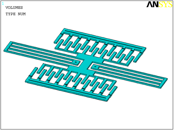
Comb drive resonators are a common application for slide film damping. Figure 5.3: Comb Drive Resonator illustrates a typical comb drive assembly consisting of fixed and moving comb drives, springs, and a central mass.
Details on the comb drive geometry are given in the input file listed below. The electrostatic behavior of the moving comb drives are represented by two TRANS126 transducer elements with prescribed Stroke vs. Capacitance data obtained from finite element runs. The structural behavior of the crab legs is modeled by a spring element. The inertial effects of the central mass are modeled with a mass element. Damping occurs between the comb teeth (lateral dimension), and between the comb teeth and the substrate (vertical dimension). Four FLUID139 elements are used to model the lateral and vertical damping (two per comb drive). The cut-off frequency is well below the frequency range for the analysis; therefore, Couette flow is assumed. Since the comb drive effective surface area changes with displacement, the DADU real constant is used (equal to the width of the plate area).
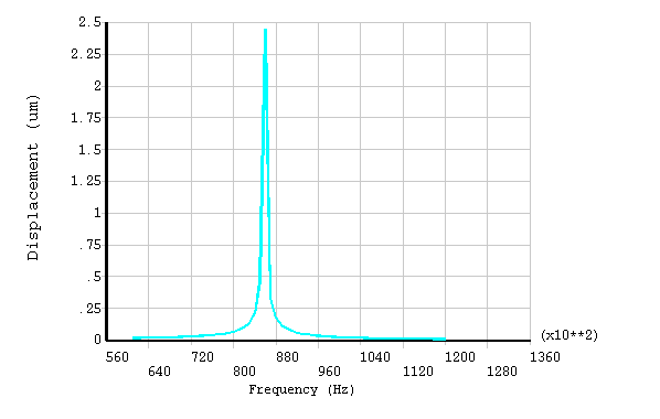
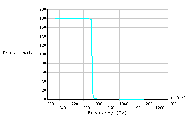
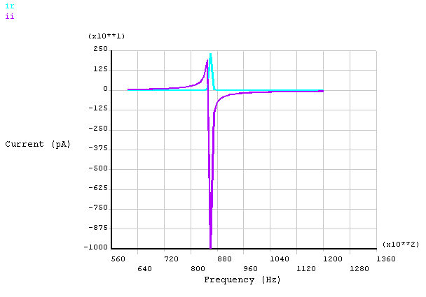
A static prestress analysis is run using a DC bias voltage on the input and output fixed comb drives. A harmonic analysis sweep is then performed using a small AC voltage. The displacement (magnitude and phase angle) of the central mass is shown in Figure 5.4: Displacement of Central Mass. Figure 5.5: Real and Imaginary Current shows the current.
/prep7
/title Comb drive resonator with FLUID139 Couette damping


!                         DRIVE COMB
!                             |
!                             |
!    CRAB LEG SPRING --- CENTRAL MASS --- CRAB LEG SPRING
!                             |
!                             |
!                        PICK-UP COMB

! Reference:
! "Microelectromechanical Filters for Signal Processing",
!  Lin, L., Howe, R.T., J. Microelectromechanical Systems,
!  VOL 7, No. 3, Sept 1998

! beam parameters (uMKS units)
E  = 190e3                        !Young modulus
d  = 2.33e-15                     ! density
hb = 2                            ! beam thickness
wb = 2                            ! beam width
Lb = 100                          ! beam length
k  = 5.699                        ! mechanical stiffness

! comb parameter
n= 9                              ! number of finger
np=n*2	                           ! number of finger pairs
x0= 10                            ! initial finger overlap
L0= 26                            ! finger length (stator comb)
L=20                              ! finger length (moving comb)
gi= L0-x0                         ! initial gap
w= 4                              ! finger width
h= hb                             ! finger thickness
gp=3                              ! finger gap (lateral)
g= 3                              ! comb gap (vertical)
Mr = 1.96563e-11                  ! mass

! Lateral gap area
areal=np*h*x0
! Vertical gap area
areav=n*w*x0

! Stroke vs. Capacitance data

x1  = 14
cx1 = 0.97857e-2
x2  = 15
cx2 = 0.96669e-2
x3  = 16
cx3 = 0.95445e-2
x4  = 17
cx4 = 0.94185e-2
x5  = 18
cx5 = 0.93384e-2

! Voltage conditions

Vi  = 40                       ! input dc bias
Vo  = 60                       ! output dc bias
Vac = 10                       ! input ac bias

! Damping parmeters

nu=18.3e-12	                    ! dynamic viscosity
po=0.1		                       ! reference pressure
dens=1.17e-18                   ! density
fc=nu/(2*3.14159*dens*(g**2))   ! cutoff frequency
daduv=w*n	             ! change in plate area - vertical
dadul=h*np            ! change in plate area - lateral

! Model

n,1,0
n,2,0
n,3,0
n,4,0

et,1,126,,0,1        !Trans126, UX-Volt DOF
r,1,,,gi,,
rmore,x1,cx1,x2,cx2,x3,cx3
rmore,x4,cx4,x5,cx5

e,1,2
e,2,3

et,2,21,,,4	                      ! Mass element
r,2,Mr
type,2
real,2
e,2

et,3,14,,1                       ! linear spring, UX DOF
r,3,k
type,3
real,3
e,2,4

! Lateral dampers
et,4,139       ! Slide-film damper, Couette flow, Continuum theory
mp,visc,4,nu
mp,dens,4,dens
r,4,g,areal,-dadul,po
type,4
mat,4
real,4
e,1,2
e,2,3

! Vertical dampers
r,5,g,areav,-daduv,po
real,5
e,1,2
e,2,3


d,1,ux,0
d,3,ux,0
d,4,ux,0
d,2,uy,0
d,2,volt,0

! Prestress static analysis

/solu
d,1,volt,Vi
d,3,volt,Vo
pstres,on
solve
fini

! Harmonic Frequency Sweep

fr0=60000
fr1=120000
/solu
antyp,harm
d,1,volt,Vac                       ! AC voltage component on capacitor
d,3,volt,0
pstres,on                          ! prestress
harfrq,fr0,fr1
nsubs,60
outres,all,all
kbc,1
solve

/post26
nsol,2,2,u,x,ux2
esol,3,2,,nmisc,24,ir
esol,4,2,,nmisc,25,ii

/axlab,x,Frequency (Hz)            ! label of x axis
plcplx,0
/axlab,y, Displacement (um)
plvar,2                   ! plot displacement  versus time (frequency)
plcplx,1
/axlab,y, Phase angle
plvar,2
plcplx,2
/axlab,y, Current (pA)
plvar,3,4
fini


