


The cyclic sector has two edges that align along the surfaces of cyclic symmetry. The edge having the algebraically lower θ in the R-θ (cylindrical) coordinate system is called the low edge and the one having the higher θ is called the high edge. The angle α between the two successive surfaces of cyclic symmetry is called the sector angle.
When setting up a cyclic symmetry analysis, the CYCLIC command defines edge components automatically, assigning them a default root name of "CYCLIC."
Optionally, you can use the CYCLIC command to define the edges and the component names manually. If you do so, you must specify a root name for the sector low- and high-edge components (line, area, or node components). A root name that you specify can contain up to 11 characters. The naming convention for each low- and high-edge component pair is either of the following:
- name_m
xxl,name_mxxh (potentially matched node patterns)
name_uxxl,name_uxxh(potentially unmatched node patterns)
The name value is the default ("CYCLIC") or
specified root name, and xx is the component pair ID number
(sequential, starting at 01).
2.2.1. CYCOPT Auto Detection Tolerance Adjustments for Difficult Cases
If the CYCLIC command fails to auto-detect the edges of your
cyclic sector, adjusting the ANGTOL and/or
FACETOL values of the CYCOPT
command may help. The most effective way to correct auto-detection is usually by
changing the ANGTOL value; however, for more difficult
cases from FEA models you may need to change FACETOL to
achieve auto detection.
When using the CYCOPT command, face tolerance, or
FACETOL, automatically defaults to 15 degrees. Face
tolerance applies only to auto-detection from node/element models that are already
meshed, and are not solid models. The default face tolerance will accommodate most
models, unless they include extreme angles or complex model geometry, both of which
can cause surface nodes to be excluded. This problem, and possible solutions are
illustrated in this section using the cyclic model shown in Figure 2.3: Full Cyclic Model.
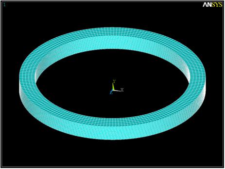
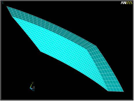
Figure 2.4: Cyclic Sector shows a cyclic sector from the model above. As
you can see, this sector model is leaning heavily in the circumferential direction.
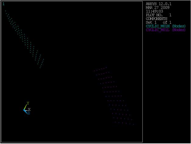
The low and high boundaries in this figure have been auto detected correctly using
the default FACETOL value of 15 deg. This successful auto
detection of these boundaries can be seen in Figure 2.5: Successful Auto Detection with Default FACETOL =
15 Deg.
If you reset the FACETOL values in the figure above
from 15 degrees to 30 degrees, auto detection fails because the logic treats the
left and bottom sides of the sector as a single face, and the top and right sides as
a second large face. This is because the bottom-left edge and top-right edge of this
model both contain a dihedral angle greater than 150 degrees (180-30), but less than
165 degrees (180-15). These large angles add to the possibility of auto-detection
errors.
If you start with a model tilted more than the sector in Figure 2.5: Successful Auto Detection with Default FACETOL =
15 Deg, it may fail at the default tolerance of 15 degrees.
This may require you to reduce FACETOL to 10 or even 5
degrees to get a successful result.
A FACETOL value that is set too low can also result in
failure. A FACETOL value that is too low can cause edges
not to be detected along element boundaries on smooth surfaces. The valid range of
FACETOL is model and mesh dependent, and may be
dictated by a single edge shared between 2 elements.
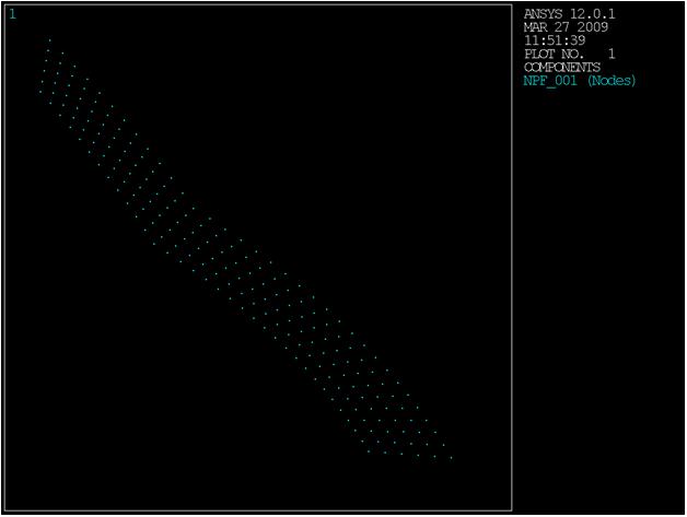
Whenever auto detect fails for an element model, save the node groups for each element face that you were working with as node components NPF_001, NPF_002, etc. for diagnostic purposes. Each node component should represent exactly one face of the cyclic sector (cyclic boundary or not).
In Figure 2.6: Auto Detection Failure Due to Large Face Tolerance , NPF_001 is clearly too large. As you can see
from the nodes, the group has leaked across the lower left edge. This indicates that
FACETOL is too large for the given dihedral
angle.
To ensure the most accurate solution, it is preferable to have identical node and element face patterns on the low and high edges of the cyclic sector. If you issue the CYCLIC command before meshing the cyclic sector (via the AMESH or VMESH command only), the mesh will have identical node and element face patterns on the low and high edges if possible. In this case, all entities must be meshed together using one meshing command.
The program allows dissimilar node patterns on the low and high edges of the cyclic sector, useful when you have only finite-element meshes for your model but not the geometry data necessary to remesh it to obtain identical node patterns. In such cases, it is possible to obtain solution (SOLVE) results, although perhaps at the expense of accuracy. A warning message appears because results may be degraded near the cyclic sector edges.
Unmatched nodes on the low- and high-edge components produce approximate cyclic symmetry solutions (as compared to matched-node cases). The program uses an unmatched-node mapping algorithm (similar to that of the CEINTF command) to connect dissimilar meshes.
The unmatched-node mapping algorithm may apply the cyclic constraint equations to nodes beyond the cyclic edges, including any nodes attached to an element touching a cyclic edge node. Since only cyclic edge nodes are automatically rotated as required during application of the cyclic constraint equations, this can lead to inaccurate results. To ensure accurate results, you must rotate all nodes attached to the elements touching edge nodes into the cyclic symmetry coordinate system using NROTAT if your analysis uses the unmatched-node mapping algorithm.
In unmatched cases, the results exhibit discontinuity across segment boundaries when expanded (via the /CYCEXPAND command). The discontinuity is an expected behavior; in the expansion process, the low edge of sector 2 lies adjacent to the high edge of sector 1, and so on throughout the full 360°.
Unmatched nodes on the edge-component pairs cannot be used for a cyclic MSUP harmonic analysis if the CYCCALC command will be used for post-processing.
For information about expanding the solution results of a cyclic symmetry analysis, see Expanding the Cyclic Symmetry Solution.
To identify the matching node pairs, you can issue a *STATUS
command to list the cyclic parameter array
Name_xref_n
(where Name is the root name of the low- and high-edge
components specified via the CYCLIC command).
The cyclic parameter array is generated internally during element plotting with cyclic expansion activated (/CYCEXPAND,,ON).
In the cyclic parameter array listing, the matching node pairs appear as a pair of node numbers with the low-edge node number having a negative value.