


ENDRELEASE
ENDRELEASE,
--, TOLERANCE,
Dof1, Dof2,
Dof3, Dof4,
KJCT, KCHECK
Specifies degrees of freedom to be decoupled for end release.
--Unused field.
TOLERANCEAngle tolerance (in degrees) between adjacent elements (
KCHECK= 0), or a percentage tolerance value for comparing cross-section properties between adjacent elements (KCHECK= 1). Default = 20.To release all selected elements, set
TOLERANCE= -1.See "Notes" for information about using this argument with
KCHECK.Dof1,Dof2,Dof3,Dof4Degrees of freedom to release. If
Dof1is blank, WARP is assumed andDof2,Dof3, andDof4are ignored.WARP
—
Release the warping degree of freedom (default).
ROTX
—
Release rotations in the X direction.
ROTY
—
Release rotations in the Y direction.
ROTZ
—
Release rotations in the Z direction.
UX
—
Release displacements in the X direction.
UY
—
Release displacements in the Y direction.
UZ
—
Release displacements in the Z direction.
BALL
—
Create ball joints (equivalent to releasing WARP, ROTX, ROTY, and ROTZ).
KJCTBehavior at a junction node (a node shared by more than two elements):
0 (or blank) – Release all elements. TOLERANCEis ignored.1 – Release noncontinuous elements (if only one pair of continuous elements exists). This argument is ignored (due to ambiguity) if
KJCT= 1 and multiple pairs of continuous elements exist.This argument is ignored if
TOLERANCE= -1.KCHECKControls how connected elements are checked at selected nodes.
0 (or blank) – Check only the angle between connected elements at the selected nodes (default). 1 – Check the angle and other cross-section properties (including offsets and orientations) between connected elements at the selected nodes. This argument is ignored if
TOLERANCE= -1.
Notes
ENDRELEASE specifies end releases for the BEAM188, BEAM189, PIPE288, and PIPE289 elements. The command works on currently selected nodes and elements.
Depending on the specified KCHECK, the
command generates end releases on any two connected elements whose angle at the connection is
> TOLERANCE, or whose cross-section properties have a difference >
TOLERANCE percent.
From within the GUI, the Picked node option
(equivalent to TOLERANCE = -1) generates an end release at the
selected node regardless of the angle of connection or cross-section properties.
When KCHECK = 1:
The specified
TOLERANCEserves as a percentage for comparing cross-section properties between adjacent elements. (For example, if using the defaultTOLERANCE= 20, the tolerance is considered to be 20 percent.)In addition to the angle between connected elements, the section integrated properties (such as area, Iyy, Iyz, Izz, warping constant, and torsion constant), offsets, and cross-section orientations are also compared at the selected nodes. If the difference in any of the properties (or angles) is >
TOLERANCE, the requested degrees of freedom are released for those nodes.For comparing cross-section orientations, the Y axes of cross-sections are compared after being projected onto the middle plane (the plane having a normal vector equal to the average of element X axes).
For comparing offsets, the differences in the centers of cross-sections are compared against the approximate maximum section size of the connected elements.
Table 108: Examples: End-Release Conditions at a Junction Node when
KJCT = 1 and KCHECK = 0
| Example Junction Node
(E – Element) | Behavior |
|---|---|
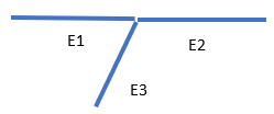 | E2 is not released. E3 is released. A new node is generated for E3. |
 | E2 and E3 are released if the angles between E1-E2 and E1-E3 are within tolerance (two continuous pairs). |
 | E2, E3, and E4 are released regardless of
KJCT (two continuous pairs). |
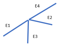 | E4 is not released. E2 and E3 are released. New nodes are generated for E2 and E3. |
Table 109: Examples: Using KCHECK with
TOLERANCE = 20
| Example (E – Element, N – Node) | Behavior when
KCHECK = 0 | Behavior when
KCHECK = 1 |
|---|---|---|
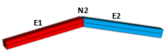 | E1 and E2 are connected at an angle > 20°, so an end release is generated at N2. | E1 and E2 have the same section properties but are connected at an angle > 20°, so an end release is generated at N2. |
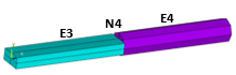 | E3 and E4 are continuous (angle between them is < 20°), so an end release is not generated at N4. | E3 and E4 use different beam sections, so an end release is generated at N4. |
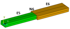 | E5 and E6 are continuous (angle between them is less than 20°), so an end release is not generated at N6. | The difference between the section properties of E5 and E6 is > 20%, so an end release is generated at N6. |
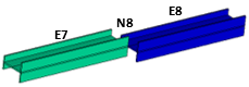 | E7 and E8 are continuous (angle between them are < 20°), so an end release is not generated at N8. | The difference between the section offsets of E7 and E8 is > 20%, so an end release is generated at N8. |
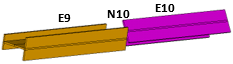 | E9 and E10 are continuous (angle between them is < 20°), so an end release is not generated at N10. | The difference between the cross-section orientations of E9 and E10 is > 20°, so an end release is generated at N10. |
To list the coupled sets generated by this command, issue CPLIST.
Exercise engineering judgement when using this command. Improper use may result in mechanics that render a solution impossible.