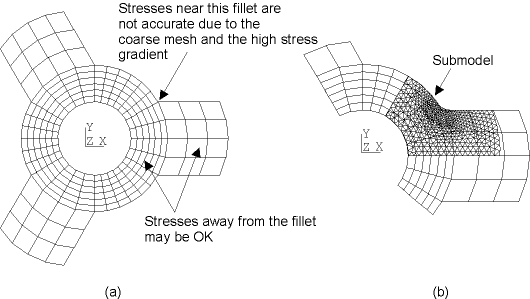
In finite element analysis, the finite element mesh is sometimes too coarse to produce satisfactory results in a specific region of interest, such as a stress concentration region in a stress analysis as shown in Figure 7.1: Submodeling of a Pulley. The figure illustrates how to deal with the problem by using submodeling to create a finer mesh on the region (submodel) of interest.
Figure 7.1: Submodeling of a Pulley

Submodeling of a pulley hub and spokes: (a) coarsely meshed model, and (b) finely meshed submodel (shown superimposed over coarse model)
Submodeling is also known as the cut-boundary displacement method (also known as the specified boundary displacement method). The cut boundary is the boundary of the submodel which represents a cut through the coarse model. Displacements calculated on the cut boundary of the coarse model are specified as boundary conditions for the submodel.
Submodeling is based on St. Venant's principle, which states that if an actual distribution of forces is replaced by a statically equivalent system, the distribution of stress and strain is altered only near the regions of load application. The principle implies that stress concentration effects are localized around the concentration; therefore, if the boundaries of the submodel are far enough away from the stress concentration, reasonably accurate results can be calculated in the submodel.
The program does not restrict submodeling to structural (stress) analyses only. Submodeling is effective in other disciplines as well. For example, in a magnetic field analysis, you can use submodeling to calculate more accurate magnetic forces in a region of interest.
Aside from the obvious benefit of yielding more accurate results in a region of your model, the submodeling technique has other advantages:
It reduces, or even eliminates, the need for complicated transition regions in solid finite element models.
It enables you to experiment with different designs for the region of interest (different fillet radii, for example).
It helps you in demonstrating the adequacy of mesh refinements.
The following restrictions apply to submodeling:
It is valid only for solid elements and shell elements.
The principle behind submodeling assumes that the cut boundaries are far enough away from the stress concentration region. You must verify that this assumption is adequately satisfied.
For load-history-dependent problems (for example, when plastic materials exist), you must cut boundary conditions from the coarse model at multiple substeps to simulate the load history dependency in the fine-mesh model analysis.
In a fine-mesh-model analysis, the cut boundary conditions must be applied as loads at multiple load steps. The more boundary cutting you do, the more accurate are the results of the fine-mesh-model analysis.


