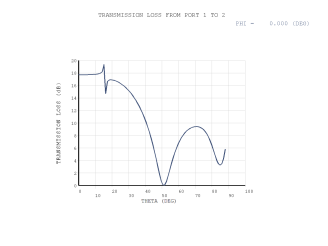
This example problem demonstrates the use of the FLUID220 element to predict the transmission loss of an infinite structural panel under excitation from an obliquely incident plane wave. The Floquet periodic boundary condition is used to truncate the infinite panel.
The material properties of the structural panel with thickness 0.0508 m are:
| Elastic moduli = 206.84 GPa |
| Minor Poisson's ratios = 0.3 |
| Mass density = 7500 kg/m3 |
The acoustic domain is the water with mass density = 1000 kg/m3 and sound speed = 1498.6 m/s.
FSI between the acoustic incident wave and the structural panel is taken into account.
Excitation and output plane wave ports are defined on the interior surfaces.
The incident angle θ (from +z axis toward +x axis) sweeps from 0° to 88° at the φ = 0° plane.
The Floquet periodic boundary condition is applied on the cell sidewalls in the x-direction.
The program calculates the phase shift on the dependent nodes according to the incident angles.
Perfectly matched layers (PML) truncate the domain in the z-direction. For more information, see Perfectly Matched Layers (PML) in the Mechanical APDL Theory Reference.
/batch, list
/nopr
/prep7
et,1,220,,                  ! coupled acoustic element
et,2,220,,1,,1              ! acoustic PML element
et,3,186                    ! structural element
rho1 = 1000                 ! acoustic fluid mass density
c01 =1498.6                 ! sound speed in acoustic fluid
rho2 = 7500                 ! structural mass density
ex=2.0684e11                ! structural Young's module
nuxy=0.3                    ! poison ratio
freq = 10000                ! working frequency
wavelen = c01/freq          ! wave length
dL=0.0508                   ! period
dd=1.0*wavelen
dpml=0.5*wavelen            ! PML thickness
h=wavelen/32                ! mesh size
p0=1                        ! amplitude of incident pressure wave
mp,dens,1,rho1              ! define acoustics material
mp,sonc,1,c01
mp,dens,2,rho2              ! define structural material
mp,ex,2,ex
mp,nuxy,2,nuxy
*dim,c,array,6              ! set up geometry
c(1)=0
c(2)=c(1)+dpml
c(3)=c(2)+dd
c(4)=c(3)+dL
c(5)=c(4)+dd
c(6)=c(5)+dpml
*do,i,1,5
block,-dL/2,dL/2,-h,h,c(i),c(i+1)
*enddo
vglue,all
vsel,s,loc,z,c(3),c(4)      ! generate mesh
type,3
mat,2
esize,h
vmesh,all
vsel,s,loc,z,c(2),c(3)
vsel,a,loc,z,c(4),c(5)
type,1
mat,1
vmesh,all
vsel,s,loc,z,c(1),c(2)
vsel,a,loc,z,c(5),c(6)
type,2
mat,1
vmesh,all
alls
nsel,s,loc,z,c(3)           ! flag FSI interface
nsel,a,loc,z,c(4)
sf,all,fsi
nsel,s,loc,x,-dL/2          ! coupled nodes
nsel,a,loc,x,dL/2
nsel,r,loc,z,c(1),c(6)
cpcyc,all,,,dL
nsel,s,loc,z,c(5)           ! define plane wave excitation at port 1
bf,all,port,1
aport,1,plan,0,p0
nsel,s,loc,z,c(2)           ! define output port at port 2
bf,all,port,2
aport,2,plan
nsel,s,loc,z,c(1)           ! pml exterior b.c
nsel,a,loc,z,c(6)
d,all,pres,0
alls
d,all,uy,0
ecpchg
fini
/solu                       ! perform solution
eqslv,sparse
pmlopt,,,,,,,1.e-7,1.e-7
antype,harmic
hropt,auto
harfrq,freq
nsub,1
msolve,88,0,88,aphi,0       ! angle theta sweep with fixed phi=0
fini
/post1
/show,png
pras,tl,all,1,,,,,1,2       ! print transmission loss
plas,tl,all,1,,,,,1,2       ! plot transmission loss
fini
The transmission loss of the structural panel under an obliquely incident plane wave is shown in this figure:


