


The pressure wave satisfies the Floquet principle if the wave propagates in a periodic structure. The infinite extension assumption allows you to investigate a single periodic unit cell as shown in the following figure.
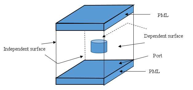
The cell sidewalls are assigned as independent and dependent boundaries, and they are bound together by the periodic boundary conditions.
To impose periodic boundary conditions, the mesh pattern on the independent boundary must be identical to the mesh pattern on the dependent boundary. You must mesh the independent boundary using the AMESH command. You then use the AGEN or MSHCOPY command to generate the mesh on the dependent boundary prior to meshing the cell volume.
Matching the nodes on the independent boundary to the nodes on the dependent boundary imposes the periodic boundary conditions. Use the CP or CPCYC command to define the independent-dependent coupled nodal pairs.
For more information on the Floquet periodic boundary condition, see Acoustic Boundary Conditions in the Mechanical APDL Theory Reference.
In a harmonic analysis, the phase shift and attenuation from the independent node to the independent node across the period should be defined on the dependent node corresponding to the independent node in the independent-dependent coupled pair. If the complex propagating constant (the phase and attenuation constant) is known on the dependent node, issue the following command:
BF,
Node,FPBC,VAL1,VAL2
On the other hand, the phase shift across the period can be calculated by the program on the dependent nodes for the plane wave incidence if a plane wave port (APORT,,PLAN command) is defined.
An obliquely incident plane wave may be launched into the unit model of the periodic structure by the APORT command; the program calculates the phase shift on the dependent node in terms of defined coupled pairs. Since multiple modes can be excited by the incident plane wave due to the discontinuity in the periodic structure, either PML or IPML (PMLOPT) should be used to truncate the domain. The interior plane wave port (APORT) launches the oblique plane wave. The port cross section is perpendicular to the z direction of the local coordinate system.
If structural elements exist with the FSI, the coupled nodal pairs and phase shift are also applied on the structural elements. It is necessary to define a small PML or IPML reflection (for example, 1.0e-6 input on the PMLOPT command) if the nearly grazing incident angle occurs. The MSOLVE command performs an angle sweep when the multiple planar wave incident angles are investigated.
In postprocessing, the PRAS and PLAS commands print and plot the frequency responses of the sound power parameters on the ports with multiple incident angles.
Example 7.13: Defining the FPBC in a Harmonic Analysis
et,1,220,,                       ! acoustic element
et,2,220,,1,,1                   ! acoustic PML element
et,3,186                         ! structural element
...
! FSI interface on both sides of structural plate
nsel,s,loc,z,strB
nsel,a,loc,z,strE
sf,all,fsi

! coupled nodes
nsel,s,loc,x,xDep
nsel,a,loc,x,xIndep
nsel,r,loc,z,zBeg,zEnd           ! all nodes on cell walls
cpcyc,all,,,(xIndep-xDep)        ! coupling nodes with period
...
nsel,s,loc,z,zPort1              ! interior port 1
bf,all,port,1
aport,1,plan,0,p0,0,0,0,theta    ! source port
nsel,s,loc,z,zPort2              ! interior port 2
bf,all,port,2
aport,2,plan,0,0,0,0,0,theta     ! output port
...
d,all,pres,0.                    ! zero pressure on PML exterior
pmlopt,,,,,,,1.e-6,1.e-6         ! PML parameter
...
In a modal analysis with FPBC, either the phase shift or the frequency is solved according to the known parameters.
The Floquet periodic boundary condition does not support acoustic fluid-structure interaction (FSI) in a modal analysis.
If the phase shift in the Floquet principle is known as 0 or  , the frequency f0 or
fπ will be the eigenvalue in the modal analysis.
On the dependent nodes, either the 0 or the
, the frequency f0 or
fπ will be the eigenvalue in the modal analysis.
On the dependent nodes, either the 0 or the  value is defined by one of the following BF
commands:
value is defined by one of the following BF
commands:
BF,
Node,FPBC,0
BF,
Node,FPBC,3.1415926535
The frequencies locate between f0 and
fπ when the phase shift varies between 0 and
 . Usually, the frequencies f0 and
fπ are solved before solving the phase shift with
a given frequency. For the phase shift
. Usually, the frequencies f0 and
fπ are solved before solving the phase shift with
a given frequency. For the phase shift  L = 0, select the block Lanczos or subspace eigensolver
(
L = 0, select the block Lanczos or subspace eigensolver
(Method = LANB or SUBSP on the
MODOPT command). For the phase shift  L =
L =  , select the unsymmetric eigensolver
(
, select the unsymmetric eigensolver
(Method = UNSYM on the MODOPT
command).
Example 7.14: Solving Frequency Eigenvalue in a Modal Analysis with FPBC
et,1,220,,                       ! acoustic element
...
! coupled nodes
nsel,s,loc,x,xDep
nsel,a,loc,x,xIndep
nsel,r,loc,z,zBeg,zEnd           ! all nodes on cell walls
cpcyc,all,,,(xIndep-xDep)        ! coupling nodes with period
...
nsel,s,loc, x,xDep               ! select dependent nodes
bf,all,FPBC,3.1415926            ! define phase shift
...
/solu
modopt,unsym,2,1.e-7,50000       ! select unsymmetric eigensolver
...
In practical design, the dispersion relationship of the periodic structure
between propagating constant and frequency is often required, which shows the
banded periodical filtering property. The frequency solution is no longer
available when the phase shift is not 0 or  since the complex value derived from the phase shift leads to
a frequency-dependent damping matrix in the eigenvalue matrix equation that
cannot be solved by a standard eigenvalue solver. The alternative is to
construct a new eigen equation taking the phasor
since the complex value derived from the phase shift leads to
a frequency-dependent damping matrix in the eigenvalue matrix equation that
cannot be solved by a standard eigenvalue solver. The alternative is to
construct a new eigen equation taking the phasor  as the eigenvalue with a given working frequency.
To flag the dependent nodes, issue the following BF command:
BF,
Node,FPBC,YES
The working frequency is defined by the MODOPT command:
MODOPT,
Method,NMODE,FREQB,FREQE,Cpxmod,Nrmkey,ModType,BlockSize, --, --, --,FREQMOD
For the phasor  eigenvalue, select the unsymmetric eigensolver
(
eigenvalue, select the unsymmetric eigensolver
(Method = UNSYM on the MODOPT
command).
Example 7.15: Solving the Phasor Eigenvalue in a Modal Analysis with FPBC
et,1,220,,                       ! acoustic element
...
! coupled nodes
nsel,s,loc,x,xDep
nsel,a,loc,x,xIndep
nsel,r,loc,z,zBeg,zEnd           ! all nodes on cell walls
cpcyc,all,,,(xIndep-xDep)        ! coupling nodes with period
...
nsel,s,loc, x,xDep               ! select dependent nodes
bf,all,FPBC,YES                  ! flag dependent nodes
...
/solu
modopt,unsym,2,1.e-7,2,,,,,,,200 ! define unsymm. solver and frequency
...